Vcm-x expansion module wiring, 4 binary input expansion module, Vcm-x component & systems wiring – Orion System VCM-X E-BUS Component User Manual
Page 47
VCM-X Component & Systems Wiring
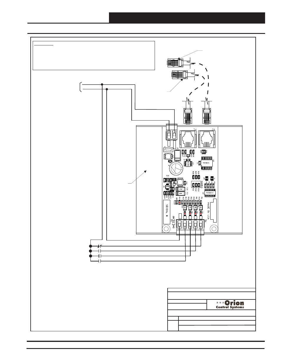
VCM-X Expansion Module Wiring
47
FILENAME
DATE:
S. Olson
DESCRIPTION:
PAGE
JOB NAME
OVCMX-BinInput-4BIN-1A.CDR
1 of 1
Modular Cable
Connect To VCM-X
E-BUS Controller
Modular Cable
Connect To Next
Expansion Board
(When Used)
24 VAC
GND
5 VA Minimum Power Required
For 4 Binary Input Expansion
Module
WARNING!!
Observe Polarity! All boards must be wired with GND-to-GND and 24VAC-to-
24VAC. Failure to observe polarity will result in damage to one or more of the
boards. Expansion Modules must be wired in such a way that the expansion
modules and the controller are always powered together. Loss of power to
the expansion module will cause the controller to become inoperative until
power is restored to the expansion module.
Dirty Filter - N.O. Contact
Proof Of Flow - N.O. Contact
Remote Forced Occupied - N.O. Contact
Emergency Shutdown - N.C. Contact
BI3
BI4
COM
BI1
GND
24 VAC
BI2
OE356-00-BI
4 Binary
Input
Expansion
Module
BI1
BI2
BI3
BI4
COM
VCM BIN EXP
BOARD
YS102364 REV1
24V
AC
GND
PWR
01/10/13
VCM-X Expansion Module
Binary Inputs On 4 Binary Input Module
4 Binary Input Expansion Module
Figure 28: OE356-00-BI 4 Binary Input Expansion Module Wiring