Add-on devices, Vcm-x component & systems wiring 86 – Orion System VCM-X E-BUS Component User Manual
Page 86
VCM-X Component & Systems Wiring
86
Add-On Devices
FILENAME
DATE:
B. Crews
DESCRIPTION:
PAGE
DRAWN BY:
Using Standard Lighting Relays
JOB NAME
05/12/04
W-LightingPnlStd1.CDR
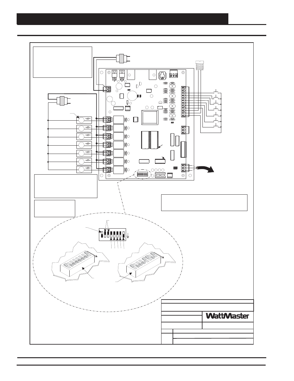
OE310-21-LP Lighting Panel Controller Wiring
1
1.)24 VAC Must Be Connected So
That All Ground Wires Remain
Common.
3.)All Communication Wiring To Be 18
Ga. Minimum, 2 Conductor Twisted
Pair With Shield. Belden #82760 Or
Equivalent.
4.)It Is Recommended That All
Controllers Address Switches Are
Set Before Installation.
2.)All Wiring To Be In Accordance With
Local And National Electrical Codes
and Specifications.
Local Loop RS-485
Communications To Other
Controllers On The Local
Loop
Note:
All Circuit Board Contacts Are N.O.
All Contacts Are Rated For 2 Amps @
24VAC Pilot Duty Only
Do Not Apply Any Voltage Greater Than
24VAC
!
!
!
EPROM
RAM
PAL
PIN 1
PIN 1
CPU
+V
+V
1
3
4
5
6
7
8
G
G
2
ANALOG
INPUTS
GND
SIG
+5V
ANALOG
OUTPUTS
A1
A2
G
T
SH
R
GND
24VAC
OE310-21-LP
Lighting Panel Controller
Light Circuit 1
Light Circuit 2
Light Circuit 3
Light Circuit 4
Light Circuit 5
Light Circuit 6
Light Circuit 7
T
SH
R
K1
K2
K3
K4
K5
K6
K7
Light Sensor (Optional)
Momentary Pushbuttons
(Optional)
Override Circuit #1
Override Circuit #2
Override Circuit #5
Override Circuit #3
Override Circuit #6
Override Circuit #4
Override Circuit #7
Line Voltage
Line Voltage
See Note 1
16
8
4
2
1
Address Switch Shown Is
Set For Address 1
Address Switch Shown Is
Set For Address 13
Controller
Address Switch
This Switch Must Be
In The ON Position
As Shown
These Switches Should Be
In The OFF Position
As Shown
ADD
ADD
ADD
The Address For Each Controller
Must Be Unique To The Other Controllers
On The Local Loop
Required VA For Transformer
Each Controller = 25VA Max.
C1
C2
C3
C4
C5
C6
C7
Lighting Contactors Or
Pilot Duty Relays
(By Others)
All Lighting Contactors
Must Be Wired For N.C.
Operation So That System
Fails To Lights On Mode.
Caution: If Lighting Contactor Coil Current
Draw Is More Than 2 Amps And/Or Does
Not Use A 24VAC Coil, A Pilot Duty Relay
That Has A Current Draw Of Less Than 2
Amps @ 24VAC Must Be Used To Energize
The Lighting Contactor. A Separate
Transformer Rated For The Total Lighting
Contactor(s)Or Pilot Relay Current Draw
Must Always Be Used To Power The Circuit.
24V
GND
Note:
Set-up, Programming And Monitoring Of The Lighting
Panel Controller Requires The Use Of A Personal
Computer And Prism Software.
Caution!
Controller Must Have Address Switch Set Between 1 And 60
C
O
N
T
R
O
L
S
Lighting Panel Wiring For Standard Lighting Contactors
Figure 63: OE310-21-LP Lighting Panel Controller Wiring