Vcm-x expansion module wiring, 12 relay expansion module, Vcm-x component & systems wiring 56 – Orion System VCM-X E-BUS Component User Manual
Page 56
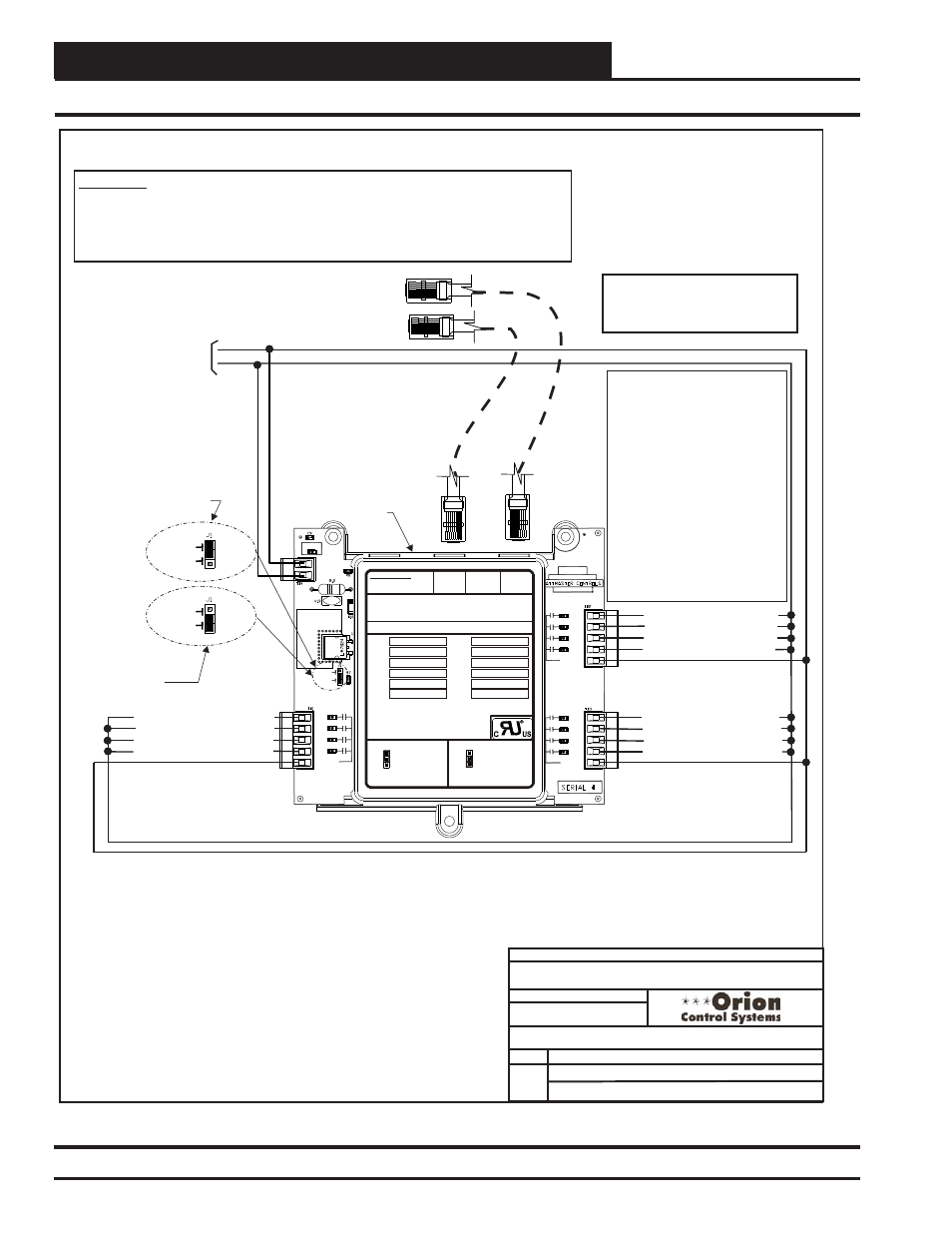
VCM-X Expansion Module Wiring
VCM-X Component & Systems Wiring
56
12 Relay Expansion Module
FILENAME
DATE:
S. Olson
DESCRIPTION:
PAGE
JOB NAME
OVCMX-12RelayWire-1A.CDR
1 of 1
01/11/13
VCM-X Controller Wiring Detail
12 Relay Expansion Module
EXP1
EXP1
EXP2
EXP2
Set Jumper As
Shown Above When
Both The 12 Relay &
VCM-X Expansion
Module Are Used
OE358-23-12R
12-Relay
Expansion Module
Set Jumper As Shown
Below When Only The
12 Relay Expansion
Module Is Used
POWER
RLY1
RLY2
RLY3
RLY4
RLY COM
EXP1
EXP2
24VAC
GND
EXPANSION BOARD
YS102228 REV 1
RELAY
RLY5
RLY6
RLY7
RLY8
RLY COM
RLY9
RLY10
RLY11
RLY12
RLY COM
MADE IN USA
SET JUMPER AS
SHOWN WHEN
THE 12 RELAY
EXPANSION MODULE
IS USED
ONLY
SET JUMPER AS
SHOWN WHEN BOTH
THE VCM EXPANSION
MODULE AND THE
RELAY EXPANSION
MODULE ARE USED
J1
J1
EXP1
EXP1
EXP2
EXP2
NOTE:
IT IS RECOMMENDED THAT YOU WRITE THE
DESCRIPTION OF THE RELAY OUTPUTS YOU
ARE CONNECTING TO THE RELAY EXPANSION
MODULE IN THE BOXES PROVIDED ABOVE
USING A PERMANENT MARKER (SHARPIE)
FOR FUTURE REFERENCE.
®
WattMaster Label
#LB102043
I2C
EXPANSION
I2C
EXPANSION
24 VAC POWER ONLY
WARNING! POLARITY MUST BE
OBSERVED OR THE BOARD
WILL BE DAMAGED
www.orioncontrols.com
RLY 1 =
RLY 7 =
RLY 2 =
RLY 8 =
RLY 3 =
RLY 9 =
RLY 4 =
RLY 10 =
RLY 5 =
RLY 11 =
RLY 6 =
RLY 12 =
OE358-23-12R-A 12 RELAY EXPANSION MODULE
Configurable Relay Output #9
Configurable Relay Output #1
Configurable Relay Output #5
R9
R1
R5
R10
R2
R6
R11
R3
R7
R12
R4
R8
Configurable Relay Output #10
Configurable Relay Output #2
Configurable Relay Output #6
Configurable Relay Output #11
Configurable Relay Output #3
Configurable Relay Output #7
Configurable Relay Output #12
Configurable Relay Output #4
Configurable Relay Output #8
Relay Output Contacts R1 Thru R12
May Be User-Configured For The
Following:
Note:
-
1 - Heating Stages
2 - Cooling Stages
3 - Warm-up Mode Command (VAV
Boxes)
4 - Reversing Valve (Heat Pumps)
5 - Reheat Control (Dehumidification)
6 - Exhaust Fan Interlock
7 - Preheater For Low Ambient Protection
8 - Alarm
9 - Override
10 - Occupied
11 - OA Damper
12 - Heat Wheel
13 - Emergency Heat
A Total Of 20 Relays Are Available
By Adding Relay Expansion Modules. All
Expansion Module Relay Outputs Are
User Configurable As Listed Above.
15 VA Minimum Power
Required For
12 Relay Expansion
Module
Note:
All Relay Outputs Are Normally Open
And Rated For 24 VAC Power Only.
1 Amp Maximum Load.
Modular Cable
Connect To VCM-X E-BUS Controller
Modular Cable
Connect To Next Expansion Board
(When Used)
24 VAC
GND
WARNING!!
Observe Polarity! All boards must be wired with GND-to-GND and 24VAC-to-24VAC.
Failure to observe polarity will result in damage to one or more of the boards. Expansion
Modules must be wired in such a way that the expansion modules and the controller are
always powered together. Loss of power to the expansion module will cause the controller
to become inoperative until power is restored to the expansion module.
Figure 37: OE358-23-12R - 12 Relay Expansion Module Wiring