Communication devices, Remote job-site computer connections & wiring, Vcm-x component & systems wiring 79 – Orion System VCM-X E-BUS Component User Manual
Page 79: Figure 57: remote job-site computer connection
VCM-X Component & Systems Wiring
79
Communication Devices
Personal Computer
(By Others)
with Prism 2 Software Installed
1
10 V
AC T
o
24 V
A
C
Power Pack
(Supplied W
ith CommLink IV)
Connect
T
o
MiniLink PD Network
T
erminals (When Used)
Otherwise Connect to VCM-X E-BUS
Controller Communications
T
erminal
SHLD
T
R
T
ypical T
erminal Blocks.
All W
iring
T
o
Be T T
o
T
, SHLD (G) T
o
SHLD
(G) & R T
o
R
T
G
R
485 LOOP
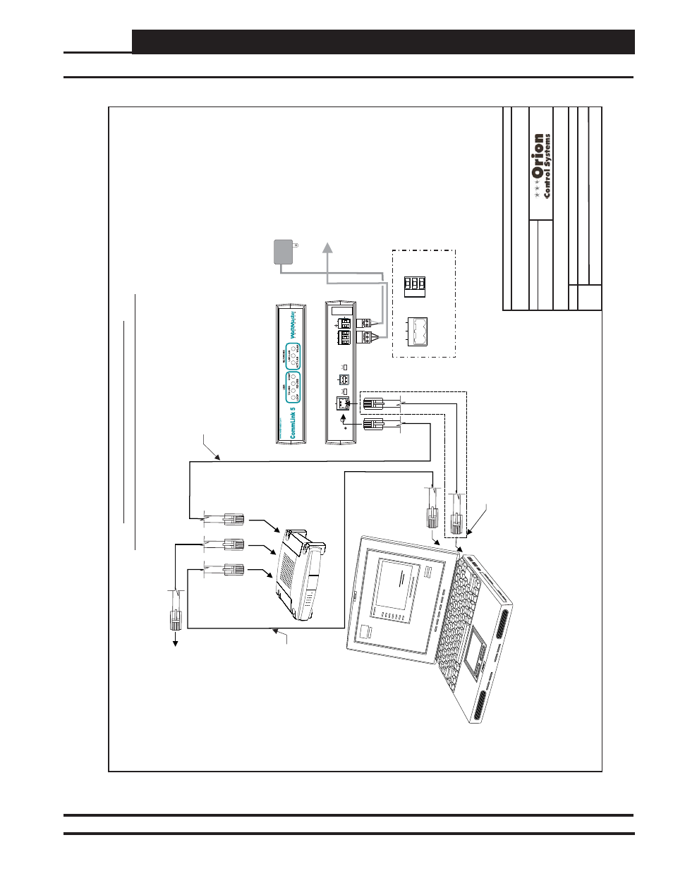
Optional Computer Connection Diagram
Using IP-Module For Job-Site Location Connection
FILENAME
DA
TE:
S. Olson
DESCRIPTION:
P
AGE
BY
:
Wiring & Connection Diagram
JOB NAME
1 of 1
01/04/13
O-VCMX-IP-Mod-Computer-1A.CDR
VCM-X IP
Module Job Site Computer Connections
Firewall
/
/Proxy Router/Modem
(By Others)
CA
T5 Crossover Ethernet Cable
(Supplied With IP
Module)
Used For Setting IP
Address On CommLink 5.
See IP
Module
T
echnical Guide Supplied With IP
Module For Software & Installation Details. Remove
Crossover Cable
After Setting IP
Address
And
Connect CommLink 5
T
o Firewall, Proxy
, Router Or
Modem (By Others)
As Desired Using Standard
CA
T5 Ethernet Cable (By Others)
CA
T5 Ethernet
Cable (By Others)
CA
T5 Ethernet
Cable (By Others)
CA
T5 Ethernet
Cable (By Others)
T
o
Next Node On
Building LAN Or W
A
N
w/IP
Module Installed
(Front V
iew)
CommLink 5
Serial #
COMPUTER
USB
10/100
ETHERNET
DIAG
485 LOOP
POWER
ACT
LNK
HIGH
LOW
BAUD
R(+)
24V
GND
SHLD
T(
-)
MULT
IPLE
SINGLE
LOOP
(Back V
iew)
Figure 57: Remote Job-Site Computer Connection
Remote Job-Site Computer Connections & Wiring