Communication devices, Vcm-x component & systems wiring 81, Philips – Orion System VCM-X E-BUS Component User Manual
Page 81: Commlink t erminals, 24 v a c class 2 t ransformer
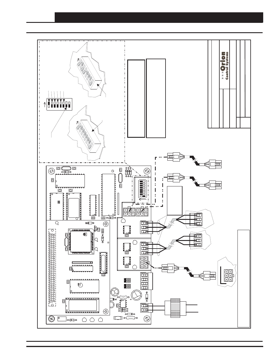
VCM-X Component & Systems Wiring
81
Communication Devices
Component
Wiring
Diagram
02/03/04
O-MiniLinkPolDevW
r1A.CDR
OE364-22
MiniLink
Polling
Device
1o
f2
CommLink
T
erminals
Only
One
MiniLink
PD
T
o
Be
Connected
T
o
CommLink.
24
V
A
C
Class
2
T
ransformer
Rated
For
6
V
A
Load
Minimum
Not
Used
HV
AC
Unit
Controller
T
erminals
(See
Note
3)
Power/Comm
Board
“IN”
Modular
Connector
(See
Note
3)
Connect
T
o
P3
or
P5
Connector
On
Previous
Minilink
PD
Connect
T
o
Connector
On
Next
Minilink
PD
P3
or
P5
EPROM
U3
U5
RAM
CX2
1
U2
R1
C3
U4
CX3
CX4
YS101818P552
PROCESSORPBOARD
CX5
C1
U1
R2
CX1
CX6
WDOG
U6
PHILIPS
D1
P1
X1
C2
C4
0-10V
4-20mA
THERM
R27
R31
D4
GND
GND
24VAC
24VAC
TB1
D5
C1
1
U12
LED
2
POWER
V1
R25
R26
C7
CX15
CX13
PROC.
DRIVER
LOOP
DRIVER
LOCAL
LOOP
GND
AIN2
AIN1
+5V
TB2
P4
P2
COMM
IN
OFF=0-5V
AIN2
AIN1
0-10V
4-20mA
THERM
TB3
U15
LD5
LD6
U13
C8
LED
1
RV
1
R4
VREF
CX2
U1
1
YS101900PMINILINK
POLLING
DEVICE
REV
.
1
OFF
1
2
4
8
16
32
CX14
NETWORK
DRIVER
RN3
SHLD
SHLD
SHLD
T
T
G
T
T
TB4
R
R
485
LOOP
R
R
U14
NETWORK
LOOP
P5
ADD
P3
R24
LD4
C9
U10
RN2
SW1
R30
X2
R29
R28
C10
U6
CX6
CX1
U7
U1
X1
C3
C1
R3
CX7
Line
V
olt
age
16
32
8
4
2
1
Address
Switch
Shown
Is
Set
For
Address
1
Address
Switch
Shown
Is
Set
For
Address
13
Controller
Address
Switch
This
Switch
Should
Be
In
The
OFF
Position
As
Shown
Note:
The
Power
T
o
The
MiniLink
PD
Must
Be
Removed
And
Reconnected
Af
ter
Changing
The
Address
Switch
Settings
In
Order
For
Any
Changes
T
o
T
ake
Ef
fect.
Caution
Disconnect
All
Communication
Loop
Wiring
From
The
MiniLink
PD
Before
Removing
Power
From
The
MiniLink
PD.
Reconnect
Power
And
Then
Reconnect
Communication
Loop
Wiring.
ADD
ADD
ADD
The
Address
For
Each
MiniLink
PD
Must
Be
Unique
T
o
The
Other
MiniLink
PDs
On
The
Network
Loop
And
Be
Between
1
and
60
FILENAME
DA
TE:
B.
Crews
DESCRIPTION:
PA
G
E
DRA
W
N
B
Y
:
JOB
NAME
Communication
Wiring
T
o
Be
Wired
T
to
T
,
SHLD
(G)
to
SHLD
(G
)&Rt
oR
MiniLink
Polling
Device
-
W
iring
Using
Power/Comm
Cables
Note:
All
Communication
Wiring
Not
Utilizing
Modular
Cable
Assemblies
Should
Be
Wired
Using
18
Ga.
Min.
2
Conductor
T
wisted
Pair
With
Shield
Belden
#82760
Or
Equivalent.
Notes:
1.)
All
Wiring
T
o
Be
In
Accordance
With
Local
And
National
Electrical
Codes
And
S
pecifications.
2.)
All
Modular
Power/Comm
Cables
Are
T
o
Be
W
attMaster
Part
Number
PCC-XX
Or
PCCE-XX
Cables.
3)
Connection
T
o
The
Power/Comm
Board
And/Or
Other
MiniLink
PDs
Can
Be
Made
By
Using
The
Local
Loop
Modular
Connector
As
Shown
On
Page
1
O
r
By
Using
2
Conductor
With
Shield
Communication
Wires
As
Shown
On
Page
2.
Connections
T
o
The
HV
AC
Unit
Controller
Must
Be
Made
By
Using
2
Conductor
With
Shield
Communication
Wires
Only
.
MiniLink Polling Device Wiring Using Modular Connectors
Figure 59: OE364-22 MiniLink Polling Device Wiring Using Modular Connectors