Add-on devices gpc-xp controller wiring, Vcm-x component & systems wiring 89, Ao ut 1 -2 – Orion System VCM-X E-BUS Component User Manual
Page 89: Gpc-xp controller wiring, Warning, Line voltage, All communication loop wiring is straight through, 1 of 1
VCM-X Component & Systems Wiring
89
Add-On Devices
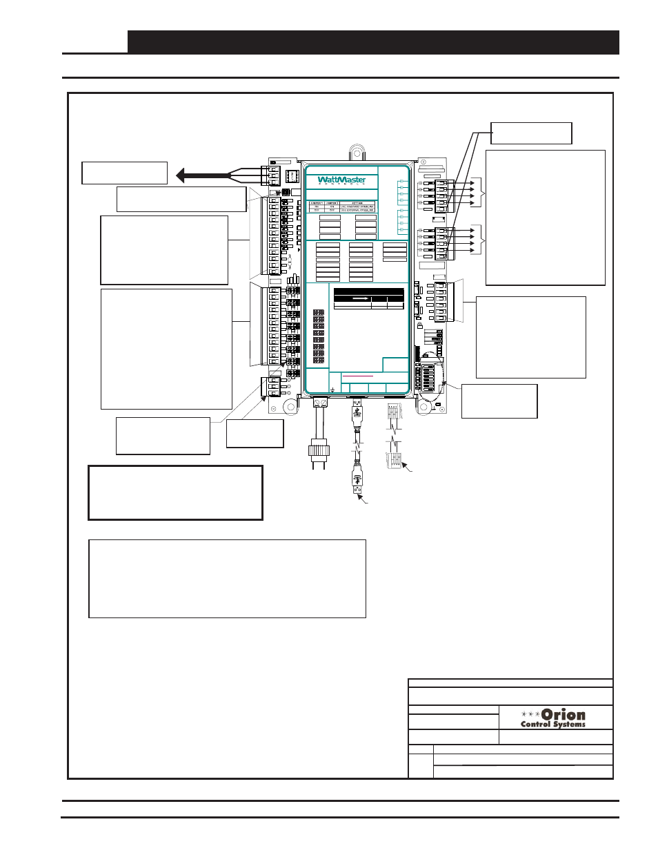
GPC-XP Controller Wiring
Figure 66: OE332-23-GPCXP GPC-XP Controller Wiring
1.)24 VAC Must Be Connected So
That All Ground Wires Remain
Common.
3.)All Communication Wiring To Be 18
Ga. Minimum, 2 Conductor Twisted
Pair With Shield. Belden #82760 Or
Equivalent.
4.)It Is Recommended That The
Address Switch Is Set Before
Installation.
2.)All Wiring To Be In Accordance With
Local And National Electrical Codes
and Specifications.
Line Voltage
All Communication Loop Wiring Is
Straight Through
24 V
A
C
24 VAC
Transformer
8 VA
Minimum
GND
Local Loop RS-485
9600 Baud
Analog Inputs AI1Through AI8
Configured For the Following:
1. Thermistor 10K Ohm Type III
Temperature Sensors (Fahrenheit)
2. Thermistor 10K Ohm Type III
Temperature Sensors (Celsius)
3. 4 - 20mA User Scaled
4. 0 - 5 vdc User Scaled
5. Wall Sensor Slide Offset
6. Read Global Analog Broadcast from
another Controller
7. Communicating Temperature Sensor
8. Communicating Humidity Sensor
9. Communicating Carbon Dioxide
Analog Outputs AOUT1 through
AOUT4 Provide (4) 0-10 VDC
Outputs Configured For The
Following:
1. Not Configured
2. Direct Acting Floating Point
3. Reverse Acting Floating Point
4. Direct Acting PID
5. Reverse Acting PID
Connect To Next Device
On The Local Loop
8 Relay Outputs Are Available For
On/Off Control Of Equipment
Configured For the Following:
1. Not Configured
2. On Above / Off Below
3. On Above / On Below
4. Off Above / On Below
5. Off Above / Off Below
6. Follow Active Binary Input
7. Follow Inactive Binary Input
8. Follow Relay Output
9. Follow Schedule
10. Ventilation Control
11. Lead Relay for Lead/Lag Control
12. Lag Relay for Lead/Lag Control
Warning:
24 VAC Must Be Connected So That All
Ground Wires Remain Common. Failure To
Do So Will Result In Damage To The
Controller
T To T, R To R, SHLD To SHLD
Jumpers - Typical
Jumpers Must Be Set
Correctly For The Type Of
Input You Require.
OE338-23-GPC-XP
GPC-XP Controller
CO
M
F
R
O
M
G
ND
CUT
TO
IS
O
L
A
T
E
WATTMASTER CONTROLS
YS102432 REV 3
LOOP COMM
GND
+24V
+5V
OUTPUTS
ADDRESS
ADD
1
2
4
8
16
32
POWER
EBUS
STATUS2
STATUS1
OUTPUTS
ANALOG
SERIAL #
OUTPUTS
RELAY
SH
R+
T-
BIN8
BIN7
BIN6
BIN5
BIN4
BIN3
BIN2
BIN1
BINARY
INPUTS
INPUTS
ANALOG
0-5
v
0-10
v
4-
2
0
m
A
AO
UT
1
-2
C14
R109
TB8
U19
U17
TB7
TB6
TB4
TB3
TB2
TB1
SW1
R97
R74
R6
1
R59
R5
5
R51
R47
R4
3
R4
1
R3
8
R21
R16
R14
D13
D12
D10
D9
D8
D7
D6
C46
C36
C21
RLY1
RLY2
RLY3
RLY4
COMMON
MADE IN USA
RLY1
RLY2
RLY3
RLY4
COMMON
AOUT1
AOUT2
AOUT3
AOUT4
GND
GND
1002
1002
.1uF
.1uF
AO
UT
3
-4
GND
1002
1002
1002
1002
1002
1002
1002
1002
1002
1002
1002
1002
.1uF
.01uF
L
OOP
BAU
D
1
2
AI7
AI8
AI6
AI5
AI4
AI1
AI2
AI3
GND
GND
GND
GND
AI8
AI7
AI6
AI5
AI4
AI3
AI2
AI1
TH
E
R
M
VDC
300
300
300
300
300
300
300
300
COM
COM
COM
COM
D11
CONNEC
ON BOA
COMMLI
Binary Inputs BIN1Through BIN8
Configured for The Following:
1. Not Used
2. Normally Closed Operation
3. Normally Open Operation
4. Read Global Binary
5. Push-Button Override
6. Follow Relay
24VAC Power
For Relay Outputs
USB Cable
Connect to Computer with
Prism II Software Installed For
Stand-Alone Programming
EBC E-BUS Cable
Connect to
Communicating Sensor
5 VDC & 24VDC
Power For
Sensors
CommLink Jumpers
Both On = Use On Board CommLink
Both Off - Use External CommLink
ADDRESS Dipswitch
is Used for Setting
the Address and
Baud Rate.
RELAY CONTACT
RATING IS 1 AMP
MAX @ 24 VAC
RS-485 COMMUNICATION LOOP. WIRE
“R” TO “R”, “T” TO “T” “SHLD” TO “SHLD”
RELAY 2
RELAY 6
RELAY 1
RELAY 5
RLY 1 =
VDC
OUTPUTS
AI1 =
+ 24 VDC
+ 5 VDC
GND
BI1 =
AO1 =
AI2 =
BI2 =
AO2 =
AI3 =
BI3 =
AO3 =
AI4 =
BI4 =
AO4 =
AI5 =
BI5 =
AI6 =
BI6 =
AI7 =
BI7 =
AI8 =
BI8 =
RLY 2 =
RLY 5 =
RLY 3 =
RLY 6 =
RLY 4 =
RLY 7 =
RLY 8 =
RELAY 3
RELAY 7
RELAY 4
RELAY 8
COMMON
COMMON
USB
PORT
E-BUS
PORT
NOTES:
1.) ANALOG INPUT JUMPER SETTINGS MUST BE
SET FOR YOUR SPECIFIC INPUT DEVICE
REQUIREMENT.
2.) IT IS RECOMMENDED THAT YOU WRITE THE
DESCRIPTION OF THE INPUT, AND/OR
OUTPUTS YOU ARE CONNECTING TO THE
CONTROLLER IN THE BOXES PROVIDED ABOVE
USING A PERMANENT MARKER (SHARPIE) FOR
FUTURE REFERENCE.
®
24 VAC POWER ONLY
WARNING! POLARITY MUST BE OBSERVED
OR THE CONTROLLER WILL BE DAMAGED
www.wattmaster.com
AI1
AI2
AI3
AI4
AI5
AI6
AI7
AI8
THE
RM
4-20
mA
0-
10
V
0-
5V
ANALOG
INPUT
JUMPERS
LED BLINK CODES
LED NAME
STATUS1
STATUS2
NORMAL OPERATION
0
1
SCHEDULE OVERRIDE
0
2
OE338-23-GPC-XP
GPC-XP CONTROLLER
WattMaster Label
#LB102095
Rev.: 1C
+2
4
VA
C
GND
NOTES:
FILENAME
DATE:
DESCRIPTION:
PAGE
DRAWN BY:
JOB NAME
S. Olson
1 of 1
GPC-XP Controller Wiring
GPCXP-CNTRLWire-1A.CDR
12/27/12
OE332-23-GPC-XP