Communication devices, System manager stand-alone wiring, Vcm-x component & systems wiring 70 – Orion System VCM-X E-BUS Component User Manual
Page 70
VCM-X Component & Systems Wiring
70
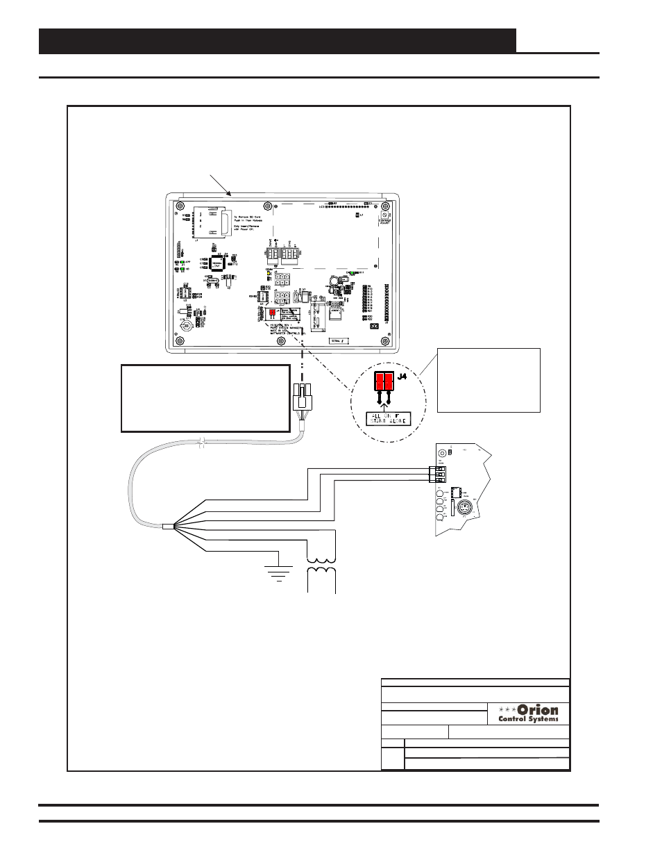
Communication Devices
Use Supplied Modular Cable
With Stripped Ends For
Connection To Terminal Block
And Transformer
WHITE (T)
DRAIN WIRE (SHLD)
BLACK (R)
RED (24 VAC)
BROWN (GND)
GREEN (GND)
Class 2 Transformer
Rated For 6 VA Minimum
Controller Board
T
SHLD
R
NOTE: If Desired A Power/Comm Board As
Used With The Networked System Can Be
Installed And Wired Instead Of Using The
Pigtail Cable Wiring Shown Below. See The
Networked System Wiring Diagram For
Details.
Modular System Manager SD
Back View
NOTE: For Stand-Alone
Installations (No CommLink
or MiniLink), All TERM
Jumpers Must Be ON.
For All Applications With
CommLink(s) Or MiniLink(s),
All Jumpers Must Be OFF.
4
GB
FILENAME
DATE:
S. Olson
DESCRIPTION:
PAGE
BY:
JOB NAME
1 of 1
09/23/2013
OE392-12 Modular System Manager
Wiring Details
Stand-Alone
O-ModSystemMgr-ModPigtail1E.cdr
System Manager Stand-Alone Wiring
Figure 48: OE392-12 Modular System Manager Stand-Alone Wiring