Vcm-x e-bus controller wiring, Vcm-x component & systems wiring 36, Zone – Orion System VCM-X E-BUS Component User Manual
Page 36
Zone
Zone
VCM-X E-BUS Controller Wiring
VCM-X Component & Systems Wiring
36
FILENAME
DATE:
S. Olson
DESCRIPTION:
PAGE
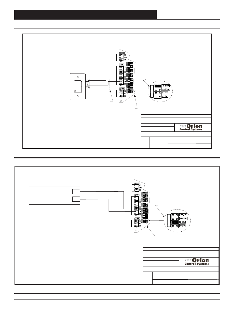
Space Temperature Sensor
JOB NAME
01/09/13
O-VCM-X-SpaceSensor-1A.CDR
VCM-X E-BUS Controller
1 of 1
GND
TMP
OE210, OE211, OE212, OE213
Space Temperature Sensor
OVR
R
E
L
O
C
R
E
M
R
O
A
W
AUX
Wire Required For
Sensors With Slide
Adjust Option Only
Note:
Either The Slide Offset Option For The Space
Temperature Sensor Or The Remote Supply
Air Temperature Reset Signal Option (By
Others) May Be Connected To An AI7 On
The VCM-X E-BUS Controller. Only One
Option Is Allowed, Not Both.
AI1
AI7
GND
AI1
AI1 SET
AI2 SET
AI3 SET
AI4 SET
AI5 SET
AI7 SET
AI2
AI3
AI4
AI5
AI7
VCM-X E-BUS Controller
Set Jumper For THERM
When Space Sensor Slide
Adjust Is Wired To AI7
AI7 SET
Space Temperature Sensor & Remote Supply Air Reset Wiring
Figure 17: OE210, OE211, OE212, OE213 Space Temperature Sensor Wiring
Figure 18: Remote Supply Air Reset Wiring
FILENAME
DATE:
S. Olson
DESCRIPTION:
PAGE
Remote Reset
JOB NAME
01/09/13
O-VCM-X-RemoteReset-1A.CDR
VCM-X E-BUS Controller
1 of 1
Remote Supply Air
Temperature Reset Signal
(By Others)
0-5 VDC or 0-10 VDC Signal
GND
Note:
Either The Slide Offset Option For The Space Temperature
Sensor Or The Remote Supply Air Temperature Reset
Signal Option (By Others) May Be Connected To AI7 On
The VCM-X E-BUS Controller. Only One Option Is Allowed,
Not Both.
AI7
GND
VCM-X E-BUS Controller
AI1
AI1 SET
AI2 SET
AI3 SET
AI4 SET
AI5 SET
AI7 SET
AI2
AI3
AI4
AI5
AI7
Regardless of Whether the Remote
SAT Reset Signal Has Been
Configured For 0-5 or 0-10 VDC,
Jumper Must Be Set For 0-10V
AI7 SET