Communication devices, Ip module installation instructions, Vcm-x component & systems wiring 77 – Orion System VCM-X E-BUS Component User Manual
Page 77: Ip-module general installation instructions
VCM-X Component & Systems Wiring
77
Communication Devices
FILENAME
DATE:
S. Olson
DESCRIPTION:
PAGE
BY:
Wiring & Connection Diagram
JOB NAME
1 of 1
IP-ModInstall1A.CDR
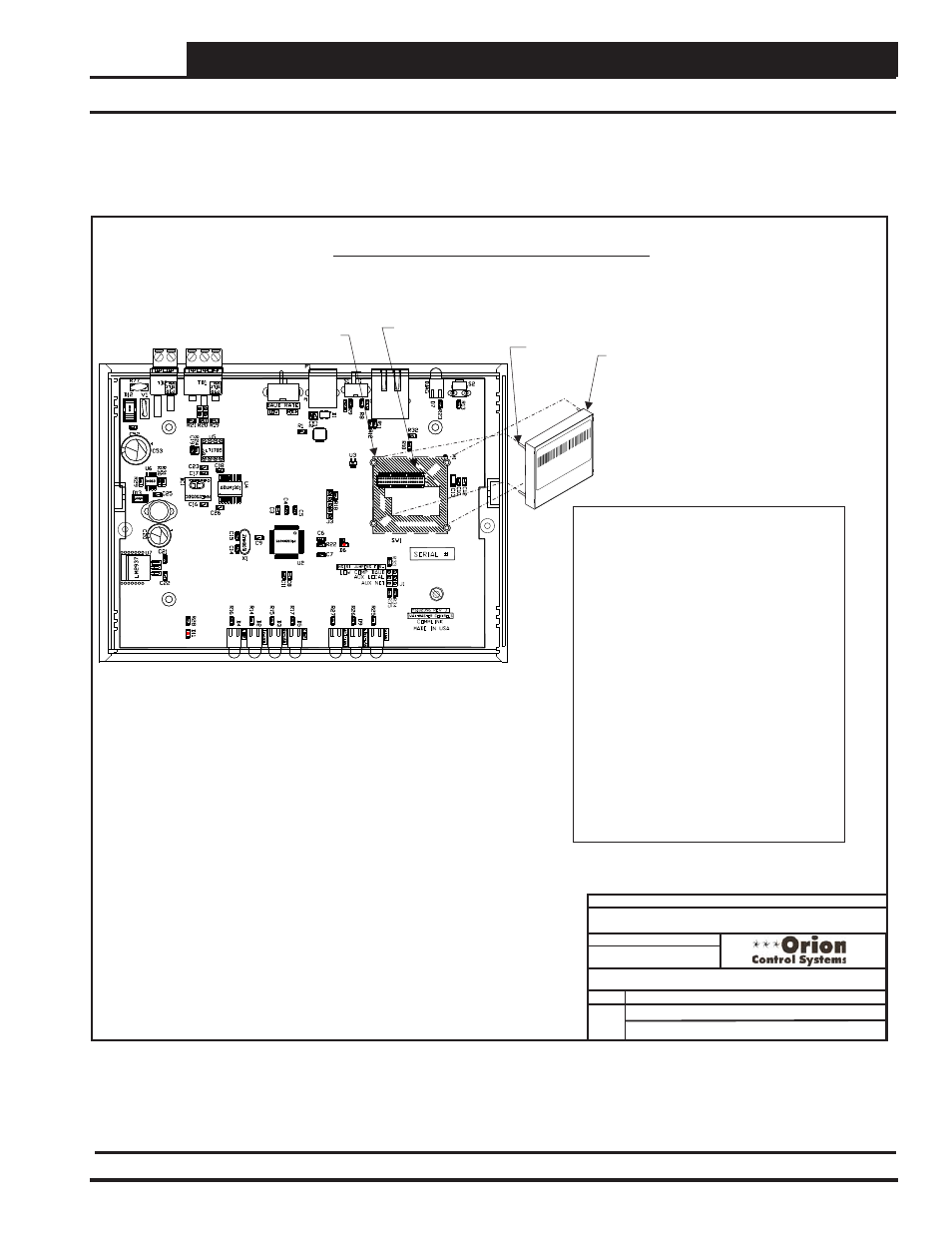
IP-Module General Installation Instructions
01/18/13
CommLink 5 IP Module Installation
Installing the OE415-02 IP Module into the CommLink 5
LANTRONIX
WiPort NR
00-20-4A-89-6B-EE
WP5001000-01 Rev
.A1
1
Pat. 4972,470 06W
21
Made in
Taiwan
IP Module Installation Instructions:
First Remove The Enclosure Screws That Hold
The Top And Bottom Of The CommLink
Enclosure Together. Remove The Top Half Of
The Enclosure To Access The Circuit Board And
IP Module Socket.
Insert The IP Module’s Guide Pins Into The
Round Pin Holes On The CommLink Circuit
Board As Shown. When The Pins Are Properly
Aligned, Press Down On The IP Module Firmly
To Seat It Into Its Socket.
After Making Sure The IP Module Is Firmly
Seated, Replace The CommLink Cover And
Secure The Enclosure Halves Back Together
With The Enclosure Screws That Were
Previously Removed.
Follow The Instructions In This Guide For
Installing The IP Module Software And
Configuring The IP Module For Your Control
System.
IP Module (Part Of
OE415-02 IP
Module Kit). Used
When TCP/IP LAN
Or Internet
Communications
With The Control
System Is Desired.
Location
Pin - Typ.
Round Pin Hole
IP Module
Socket
PIC
32
24
VA
C
GND
T
SH
R
PIC
32
24
VA
C
GND
T
SH
R
Figure 55: OE415-02 IP Module Installation Instructions
IP Module Installation Instructions