Communication devices, Usb-link 2 computer connections & wiring, Vcm-x component & systems wiring 80 – Orion System VCM-X E-BUS Component User Manual
Page 80: Optional usb-link 2 connection diagram, Figure 58: computer connections using usb-link 2, Warning observe polarity
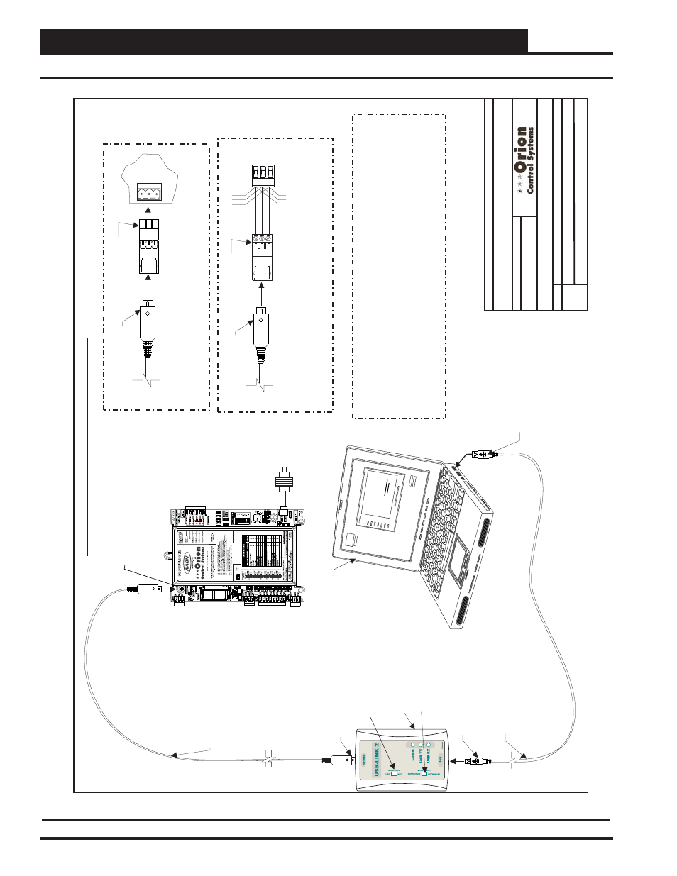
VCM-X Component & Systems Wiring
80
Communication Devices
FILENAME
DA
TE:
S. Olson
DESCRIPTION:
P
AGE
BY
:
Wiring & Connection Diagram
JOB NAME
1 of 1
Optional USB-Link 2 Connection Diagram
O-VCMX-JS-USBLINK2-1A.CDR
VCM-X Job Site USB-Link 2
01/04/13
Adapter
Supplied With USB-Link
PL101904
Adapter
Supplied With USB-Link
PL101905
Mini-DIN Cable
Mini-DIN Cable
Use
The
Adapter
T
o
Plug In
T
o
A
T
erminal Socket
And Connect
The USB-Link On Boards
That Don’t Have
A
Female Mini-DIN Plug Connection.
This Only
Allows Communications With
The Board It Is Connected
T
o
PL101904
NOTE:
.
Use
The
Adapter
And Wire
T
o
A
T
erminal Block
T
o
Connect
The USB-Link
T
o
The Local Communications Loop
All Controllers
That
Are Connected
T
o
The System
P
101905
L
On Boards
That Don’t Have
A
Female Mini-DIN Plug Connection.
This
Allows Communications With
. See Note 1.
NOTE:
USB-Link 2
Controller With
Mini-DIN Plug
USB Cable
Supplied With
USB-Link
Connect
T
ype
A
Cable End
T
o
USB Port On Desktop Or Laptop
Personal Computer
.
USB Drivers Supplied With
The USB-
Link 2 Must Be Installed On
Y
our Computer
Before USB-Link 2 Can Be Used.
NOTE:
Connect
T
ype B Cable End
T
o
USB Port On USB Link.
Connect Mini-DIN Cable End
T
o
Mini-DIN Port On USB-Link.
Communication Switch
Must Be Set
T
o
Stand
Alone
Or Network Depending On
Y
our Installation.
Mini-DIN Cable
Supplied With USB-
Link
Connect
The USB-Link
Mini
D
Cable
T
o
The
-
IN
Connector On Controllers
That
Are Supplied
With
Them.
All
Controllers
That
Are
Connected
T
o
The System
-
IN
Female
Mini
D
Plug
This
Allows
Communications With
.
See Note 1.
NOTE:
SHLD
SHLD
T
T
R
R
Computer
(By Others)
With Prism II
Software
Installed
Notes
:
1. For Networked Systems, In
The Event
That
Y
ou Have
A
CommLink II or CommLink III
And Have
An EPROM Software V
ersion Earlier
Than 3.15 Installed In
The CommLink,
,
Y
ou Will Need
An EPROM Upgrade Before
Y
ou Can
V
iew
All Controllers On
Y
our System. Contact W
attMaster
T
echnical Support For
An EPROM Update.
If
Y
ou Have
A
CommLink IV
This WIll Not Be
A
Problem.
Even Without
The EPROM Upgrade
Y
ou Can Still V
iew
A
Single Controller
T
o
Do
This
Y
ou Must First Disconnect
The Communication Loop From
The Controller
Y
our USB-Link Is
Plugged Into
Or
Y
our MiniLink
Has
An EPROM Software V
ersion Earlier
Than 3.14
Using Prism II.
. Set
The USB-Link Communication Switch
T
o
Stand
Alone, Set
The
T
ype Of CommLink In
Prism II
T
o
USB Link Stand
Alone,
And Cycle Power By Disconnecting
And Reconnecting the USB Power
Supply Cable.
Line V
oltage
VCM-X Unit Controller
24 V
A
C
(8 V
A
)
WARNING
OBSERVE
POLARITY
ST
AND
ALONE
NETWORK
Communication Speed Switch
Must Be Set
T
o
Low or High Speed
Depending on
Y
our Controller
’s
Baud Rate.
Figure 58: Computer Connections Using USB-Link 2
USB-Link 2 Computer Connections & Wiring