Vcm-x e-bus controller wiring, Supply fan vfd & bypass damper actuator, Vcm-x component & systems wiring – Orion System VCM-X E-BUS Component User Manual
Page 39
VCM-X Component & Systems Wiring
VCM-X E-BUS Controller Wiring
39
FILENAME
DATE:
DESCRIPTION:
PAGE
JOB NAME
OVCMX-ZoneByp-SFVFD-Wr1A.CDR
1 of 1
01/09/13
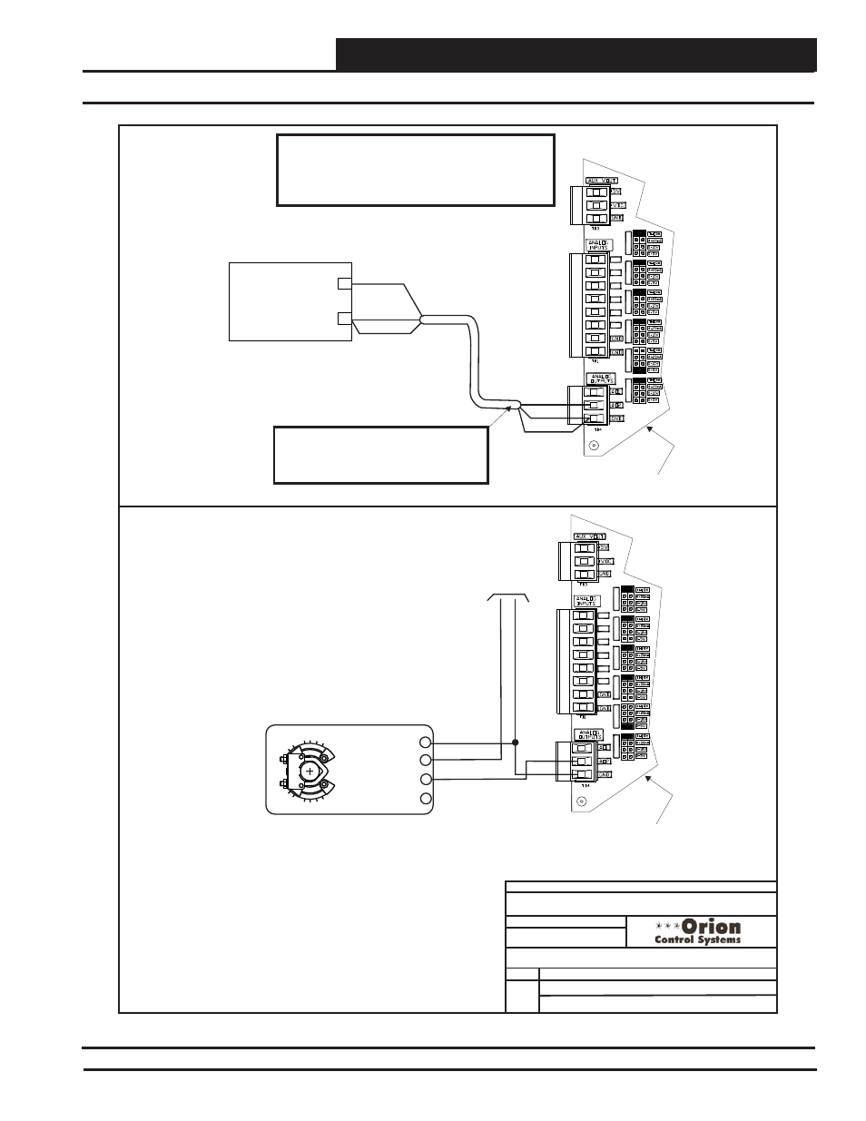
VCM-X E-BUS Controller Wiring Detail
Supply Fan VFD or Bypass Damper Actuator
+
Supply Fan Variable Frequency Drive
(By Others)
_
0-10VDC Input From AO2
Shield
GND
Caution:
The VFD Unit Must Be Configured For 0-10 VDC Input.
The Input Resistance At The VFD Must Not Be Less
Than 1000 Ohms When Measured At The VFD
Terminals With All Input Wires Removed.
Note:
Wire To The VFD Using 18 GA Minimum 2
Conductor Twisted Pair With Shield Cable.
Wire Shield To GND As Shown
AO2
GND
Shield
VCM-X E-BUS Controller
AI1
AI1 SET
AI2 SET
AI3 SET
AI4 SET
AI5 SET
AI7 SET
AI2
AI3
AI4
AI5
AI7
Bypass Damper Actuator
(Belimo Actuator Shown)
0-10 VDC
24 VAC Power Source
Sized For Actuator VA Load
GND
24 VAC
3 (Y)
5 (U)
2 (+)
1 (-)
Belimo Actuator Wiring
Shown. Consult Factory For
Other Manufacturer Wiring
Instructions
VCM-X E-BUS Controller
GND
AO2
AI1
AI1 SET
AI2 SET
AI3 SET
AI4 SET
AI5 SET
AI7 SET
AI2
AI3
AI4
AI5
AI7
Note:
Either The Supply Fan VFD Or
The Bypass Damper Actuator
May Be Connected To AO2 On
The VCM-X E-BUS Controller.
Only One Option Is Allowed,
Not Both.
Note:
Either The Supply Fan VFD Or
The Bypass Damper Actuator
May Be Connected To AO2 On
The VCM-X E-BUS Controller.
Only One Option Is Allowed,
Not Both.
S. Olson
Supply Fan VFD & Bypass Damper Actuator
Figure 22: Supply Fan VFD & Bypass Damper Actuator Wiring