System installation, Vcm-x component & systems wiring 8, Wiring considerations – Orion System VCM-X E-BUS Component User Manual
Page 8: Power/comm board requirements
VCM-X Component & Systems Wiring
8
System Installation
Wiring Considerations
Before beginning installation, please study the wiring diagrams
for the controllers you are using with your particular application.
These diagrams appear in this manual and can also be found in the
technical guides supplied with your specifi c controllers. Wire and
transformer sizing instructions and examples are found in Figures
1 & 2, pages 9-10 of this manual.
The Modular VAV/Zone Controllers are equipped with modular con-
nections. Non-Modular VAV/Zone Controllers have wiring terminals
instead of modular connectors. The VCM-X E-BUS Controller
is supplied with modular connectors. The Power/Comm board is
supplied with both terminals and a modular connector on the input
side. All of its outputs use modular connectors. The Minlink Polling
Device is equipped with both modular and wiring terminal blocks.
We recommend (when possible) using modular cables instead of hard
wiring to wire terminal blocks to save installation time and eliminate
wiring errors. In some cases, however, hard wiring is unavoidable.
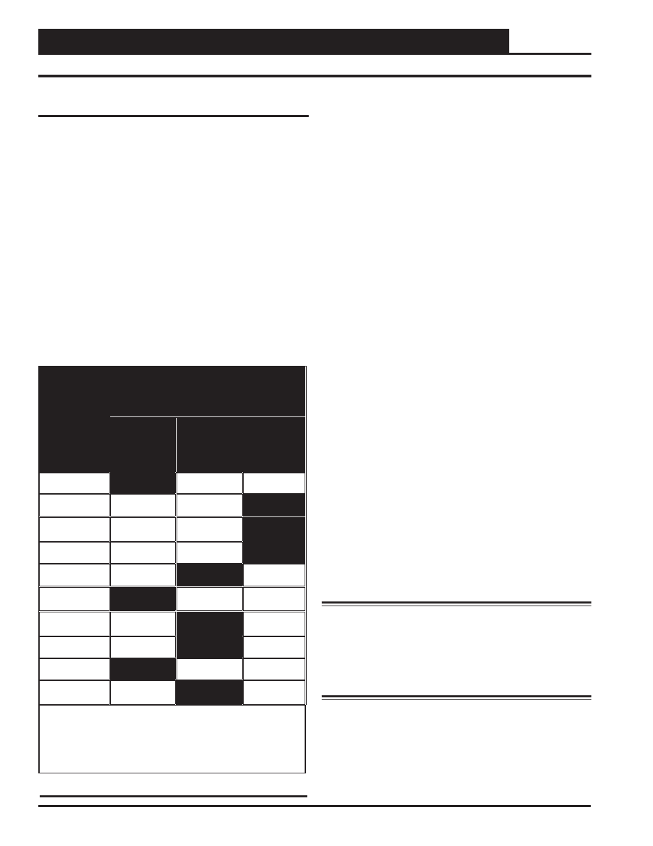
The table below lists the various Orion devices/controllers and their
available termination type(s) for communications and power wiring.
Communications And Power Wiring
Terminations For Orion Products
Orion
Controller Or
Device
Available Power And Communications
Connections
Modular
Connectors
Only
Wire
Terminals
Only
Both
Modular
Connectors
And Wire
Terminals
VCM-X E-BUS
X
VAV/Zone
•
X
Power/Comm
Board
X
MiniLink PD
X
CommLink 5
X
*Modular System
Manager
X
System Manager
TS II
X
GPC-X
X
GPC-XP
X
Lighting
Controller
X
* The System Manager is supplied with a pigtail connector that has a
modular plug on one end and stripped wires on the other end. The pigtail is
used to allow wiring connection to the HVAC unit controller wire terminals
and to a 24 VAC power transformer on systems that do not use Power/
Comm boards.
Power/Comm Board Requirements
Standard Connection Confi gurations and Use
Power/Comm boards are typically used on Networked, Single, and
Multiple Loop systems to transfer 24 VAC power and “Local Loop”
communications to Modular VAV/Zone Controllers, Modular System
Managers, or other Power/Comm boards.
The Power/Comm board must always be powered by its own dedi-
cated 24 VAC transformer connected to its 2-wire, 24 VAC input
terminals (TB1).
Local Loop communications can be transferred to the Power/Comm
Board via a modular cable connected to its “Comm In” modular
connector input terminal (P2). This modular cable connection can
originate from the “Local Loop” modular connector of the Mini-
Link PD for this loop, another Power/Comm board output on the
same loop, or a Modular VAV/Zone Controller or Modular System
Manager output on the same loop. A Power/Comm board can also
be connected if desired to the “Local Loop” by hard wiring a 2-wire
shielded cable connected between its 3-wire communications input
terminal (TB1) and a Power/Comm board, or the MiniLink PD
“Local Loop”, 3-wire communications terminal.
For detailed wiring diagrams, see the Power/Comm board wiring
diagrams in the “Communication Devices Diagrams” section of this
manual. For Power/Comm board transformer sizing, see Figures 1
& 2, pages 9-10 of this manual.
Alternative Connection Confi guration and Use
If desired, the Power/Comm board can also be used to transfer both
24 VAC power and “Network Loop” communications to multiple
MiniLink PDs. Connection between the MiniLink PD(s) and Power/
Comm board(s) is accomplished by using modular cables between
the Power/Comm board’s modular output connectors and the Mini-
Link PD(s)’s “Network Loop” modular input connectors. When a
Power/Comm board is used to connect power and communications
to MiniLink PDs in this manner, that particular Power/Comm board
cannot also be used to share communications and/or power with
Modular VAV/Zone Controllers or Modular System Manager(s).
Warning: Do not ground the 24 VAC transformer that
is to be used with the Power/Comm board. Grounding of
the transformer will damage the Power/Comm board and
all boards connected to it. A separate transformer must be
used for each Power/Comm board. No exceptions. Do not
connect any other devices to the transformer used for the
Power/Comm board!
For detailed wiring diagrams, see the Power/Comm board wiring
diagrams in the “Communication Devices Diagrams” section of
this manual.
For Power/Comm board transformer sizing, see Figures 1 & 2,
pages 9-10 of this manual.
Wiring Considerations
Table 1: Communications and Power Terminations