Cable schematics, Cable schematics -12, T1 network interface cable – Verilink APS 2000 T1 Line Protection (880-502411-001) Product Manual User Manual
Page 20
Overview
1-12
Verilink APS 2000 User Manual
Each CSU must be within the following cable distances from the
connected equipment at the customer premises:
These distances are critical for accurate system operation.
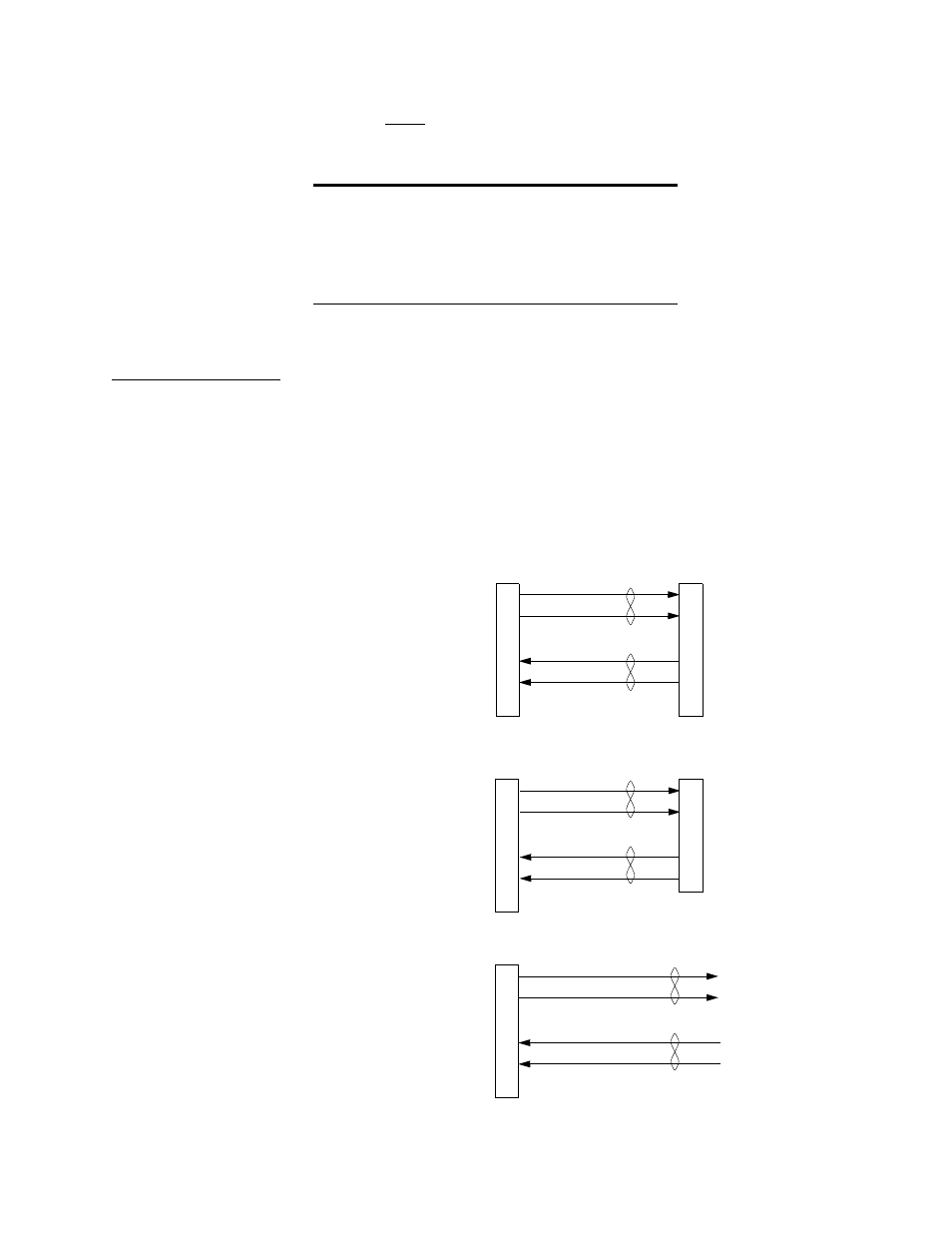
Cable Schematics
The following cable schematics will provide you with the
information to assemble any of the shelf interconnection cables.
T1 network
interface cable
The network interface cables are used to connect the SCC 2120 via
the CIM 2022 APS to the T1 network.
Figure 1-6 Network Interface Cable Schematics
CSU attached to:
Distance from CSU
DSX-1 equipment
655 feet, maximum
First network repeater
3000 feet, maximum
ASCII terminal
(RS-232D)
50 feet, nominal
To/From
CSU
To/From
CSU
To/From
CSU
To Networ
From Networ
RJ-48C
Male
RJ-48C
Male
RJ-48
Male
RJ-48C
Male
Twisted
Pairs
4
5
7
1
2
8
4
5
7
1
2
8
4
5
7
1
2
8
Ring
Tip
Ring 1
Tip 1
Ring
Tip
Ring 1
Tip 1
RJ-48C to RJ-48C
RJ-48C to DA-15 (15-Pin
RJ-48C to Open Wires
Blue (R)
Wht/Blue (T
Orn (R1)
Wht/Orn (T1)
To/From
Networ
To/From
Networ
4
5
7
2
8
DA-1
Male
9
1
11
3
1
(PN: 458-501768-xxx)
(PN: 458-501767-xxx)
(PN: 458-501769-xxx)
Twisted
Pairs
Twisted
Pairs