Scanner instruction manual, Configuration for 12 or 24 vdc power option, Transmitter supply voltage selection (p+, p-) – Precision Digital PD6080 User Manual
Page 18: Main board
PD6080/PD6081 Super Snooper Modbus
Scanner Instruction Manual
18
Configuration for 12 or 24 VDC Power Option
Warning!
Do not exceed voltage rating of the selected configuration.
Scanners equipped with the 12/24 VDC power option are shipped from the factory ready to operate
from 24 VDC.
To configure the scanner for 12 VDC power:
1. Remove all the connectors.
2. Unscrew the back cover.
3. Slide the back cover about 1 inch.
4. Configure the J9 jumper, located behind the power connector, for 12 V as shown below.
MAIN BOARD
24 VDC
12 VDC
POWER
J9
12 V
24 V
J9 CONFIGURATION
Factory
Default
M-LINK
+
_
Figure 4. Jumper Configuration for 12/24 VDC Power
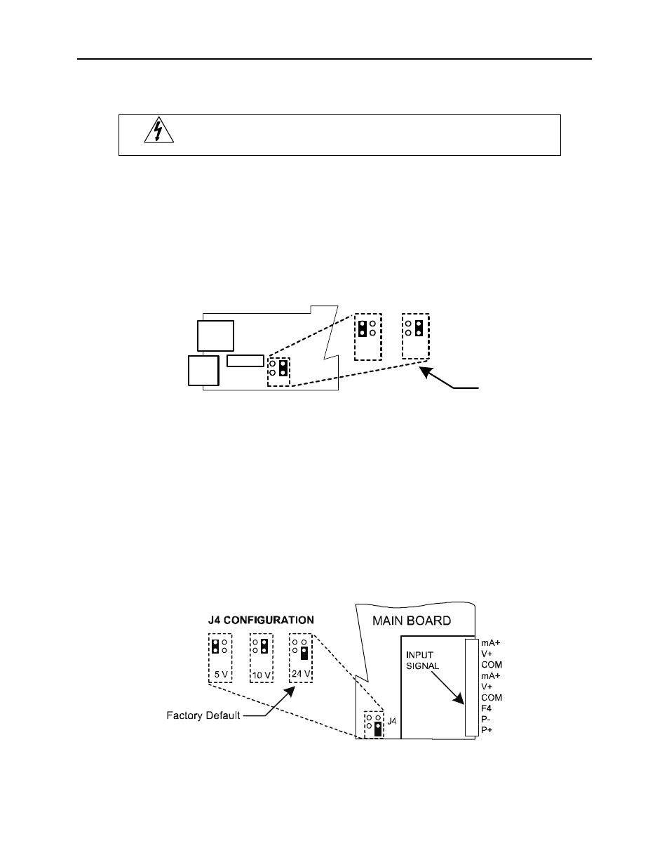
Transmitter Supply Voltage Selection (P+, P-)
All scanners, including models equipped with the 12/24 VDC power option, are shipped from the
factory configured to provide 24 VDC power for the transmitter or sensor. If the transmitter requires 5
or 10 VDC excitation, the internal jumper J4 must be configured accordingly.
To access the voltage selection jumper:
1. Remove all the wiring connectors.
2. Unscrew the back cover.
3. Slide out the back cover by about 1 inch.
4. Configure the J4 jumper, located behind the input signal connector, for the desired excitation
voltage as shown.
Figure 5. Transmitter Supply Voltage Selection