Scanner instruction manual, 40 scaling the pv display values ( scale ), Scale menu – Precision Digital PD6080 User Manual
Page 40
PD6080/PD6081 Super Snooper Modbus
Scanner Instruction Manual
40
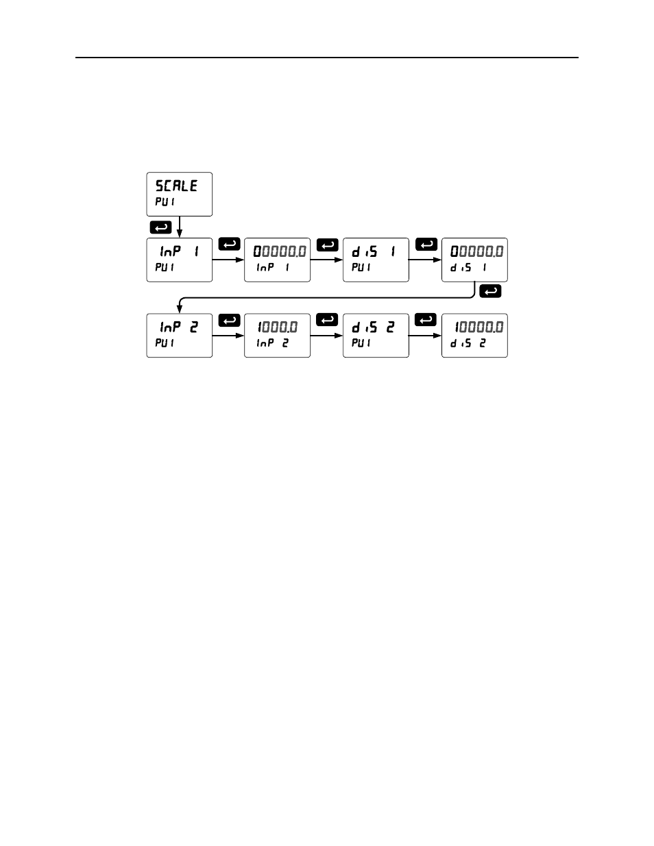
Scaling the PV Display Values (sCale)
The data that the scanner receives can be scaled to display in engineering units. Input 1 must be less
than Input 2, Input 2 must be less than Input 3, etc. (known as monotonic values). Press Enter to save
the changes or Menu to exit without saving. When the Linear function is selected for PV1 & PV2, up to 32
points may be programmed to handle non-linear data. Only two points are available for all other PVs and
for either the Square Root or Programmable Exponent functions. Round Horizontal Tanks are scaled
using the length and diameter of the tank.
Scale Menu
The display will show Error if the scaling or calibration process is unsuccessful. Undesired operation
may occur if the error is not corrected. Correct the error by either changing one of the inputs in question
or changing the number of points to exclude an erroneous input point.
Note 1: For Feet & Inches Display format, the display values will be in the format 99
FT
11
IN
15
/16th
or 8
th
.
Make the left digit for inches and 16
th
blank if the value is less than 10. Example: 50 Feet, 9
Inches, and 8/16 will be displayed as 50
FT
_9
IN
_8
16th
instead of 50
FT
09
IN
08
/16th
.
Note 2: Scaling Short and Long input values (input 1, input 2, etc.) should be done without the decimal
point.
Multi-Point Linearization (Linear)
The scanner is set up at the factory for 2-point linear scaling. Up to 32 linearization points may be
selected for PV1 and PV2. All other PVs have two linearization points available. See page 79 for details.
ScanView Software
The scanner can also be programmed using the PC-based ScanView software available for free
download at www.predig.com.
In order to configure the scanner using a computer, the scanner must be connected using an RS-485 to
USB converter or an RS-485 to RS-232 converter; see ORDERING INFORMATION on page 8.
Monitoring and data logging for one scanner (Master mode) is available with ScanView software. All the
enabled PVs and math channels may be logged to a single .csv file.
The ScanView software synchronizes with the scanner in Master mode, one second after the scanner has
completed a polling cycle.
Note: The poll time of the scanner must be greater than 5 seconds to prevent collisions on the bus.