Scanner instruction manual, Scanner mode selection operating modes ( nmode ), How to enable process variables (pvs) – Precision Digital PD6080 User Manual
Page 33
PD6080/PD6081 Super Snooper Modbus
Scanner Instruction Manual
33
Scanner Mode Selection
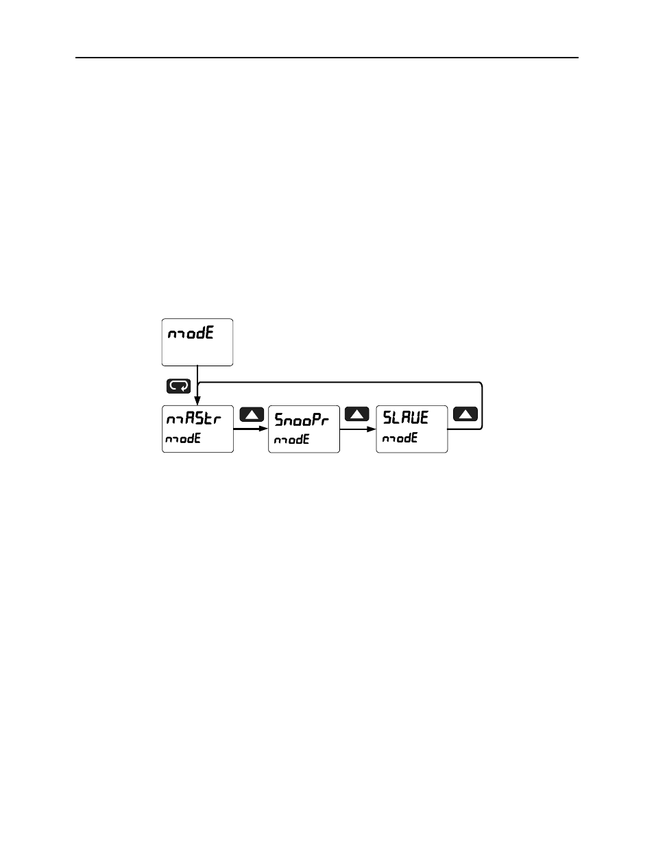
Operating Modes (nmode)
The Mode menu is used to select how the scanner is to function:
1. Master: Reads a slave device, scales the data from it, displays the result, and operates the relays
and 4-20 mA output. The Master polls from 1 to 16 process variables from 1 to 16 slave devices.
The Master processes and displays PV1 through PV16 and alternately displays the variables
being polled.
2. Snooper: Listens to the Modbus traffic and picks up a specific register or registers being polled by
a Master device from a specific slave device and processes the data being read.
3. Slave: Read and controlled by a master device (PLC, DCS, etc). The data sent to it by the master
is scaled, displayed, and used to operate the relays and 4-20 mA output.
The Master mode requires additional parameter selection to specify how the slave device is to be read
and how to interpret the data.
Press Menu to enter Scanner Programming. Press the Enter button to access any menu or press Up
arrow button to scroll through choices. Press the Menu button to exit at any time and return to Run mode.
How to Enable Process Variables (PVs)
In Master or Snooper Mode, navigate to the PV Number menu and press ENTER. From there, the user
can scroll through all of the sixteen available PVs. In order to enable a specific PV, simply press ENTER
to access the desired PV, then scroll to ENABLE and press ENTER (Follow the same course of action for
disabling PVs).
Enter the Slave ID of the device being polled by the Master, followed by the Function Code, Register
Number, Data Type, and Byte Order. Analog input channels must be assigned a Slave ID corresponding
to the input to be read as indicated here: Ch A = 256 (mA) or 257 (V), Ch B = 258 (mA) or 259 (V).
Once the desired PVs are enabled, navigate to the Setup menu and enter the PV Setup in order to select
the PV tag, units, format, and decimal point parameters, as well as to scale the PVs.
Once the user has scaled the final PV, the scanner automatically goes to the Display Setup menu to
access the Top and Bottom display assignments.
By default the top display is assigned to Display PV (d pv) and the bottom to display the Tag (d tag) for
the corresponding PV.
It is possible to display PVs & Tags on the top and bottom displays simultaneously by selecting Tag & PV
Number (tag.pvn). The top display is setup by default to display PV & tag for PV1, 3, 5, 7; while the
bottom display is setup by default to display PV & tag 2, 4, 6, 8. These can be changed by the user to
display any or all PVs. Program either the Top or Bottom display to show the desired parameters and
press ENTER. See page 41 for details.