Troubleshooting, Scanner instruction manual, Troubleshooting tips – Precision Digital PD6080 User Manual
Page 97
PD6080/PD6081 Super Snooper Modbus
Scanner Instruction Manual
97
TROUBLESHOOTING
The rugged design and the user-friendly interface of the scanner should make it unusual for the installer
or operator to refer to this section of the manual. However, due to the many features and functions of the
scanner, it’s possible that the setup of the scanner does not agree with what an operator expects to see.
If the scanner is not working as expected, refer to the recommendations below.
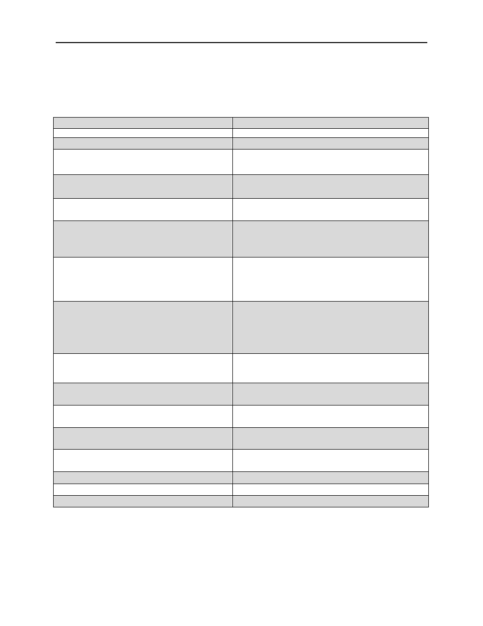
Troubleshooting Tips
Symptom
Check/Action
No display at all
Check power at power connector
Not able to change setup or programming, Locd is displayed
Scanner is password-protected, enter correct six-digit password to unlock
Scanner displays error message during scaling (Error)
Check:
Input 2 must greater than Input 1, Input 3 must be greater
than Input 2, etc.
Scanner displays
1.
999999
2.
-99999
Indicating overrange or underrange condition
Check the input data value and scaling in Setup menu
Display stop scanning,
■
LED indicator flashing
Check:
1.
Stop on alarm feature has been enabled
2.
Press PREV or NEXT to resume scanning
Displays break message
Check:
1.
RS-485 connection to slave devices
2.
Slave Id, register number of slave devices
3.
Baud rate and parity of all devices on the bus
4.
Scanner Id must be different from other devices
Snooper mode not reading the PVs on the RS-485 bus
Check:
1.
Increase Master’s Transmit Delay
(e.g. Snooper delay = 100ms, Master delay = 110ms)
2.
Increase Snooper’s byte-to-byte timeout
3.
Decrease the slave device’s transmit delay to <10ms
4.
Snooper cannot read the same PV twice, check setup
Scanner experiencing faults and communication breaks
Check:
1.
Increase response time (t-resp) and/or transmit delay
(tr dly). This may require some trial and error, as these
are dependent upon the number of devices on the bus.
2.
Internal Scan ID Modbus address. Addresses 256 (mA)
or 257 (V) are used for Channel A, while Addresses 258
(mA) or 259 (V) are used for Channel B.
Scanner not communicating with ScanView software
Check:
1.
Serial adapter and cable
2. Serial
settings
3.
Scanner address, baud rate, and transmit delay
Display does not respond to input data, reading a fixed
number
Check:
Display assignment, it might be displaying max/ min
Display reading is not accurate
Check:
1. PV
Scaling
2.
Check format selected: Dec or Ft&In
Relay operation is reversed
Check:
1. Fail-safe
in
Setup
menu
2.
Wiring of relay contacts
Relay and status LED do not
respond to signal
Check:
1.
Relay action in Setup menu
2.
Set and reset points
Flashing relay status LEDs
Relays in manual control mode or relay interlock switches opened.
If the display locks up or the scanner does not respond at all
Cycle the power to reboot the microprocessor.
Other symptoms not described above
Call Technical Support for assistance.