Scanner instruction manual – Precision Digital PD6080 User Manual
Page 24
PD6080/PD6081 Super Snooper Modbus
Scanner Instruction Manual
24
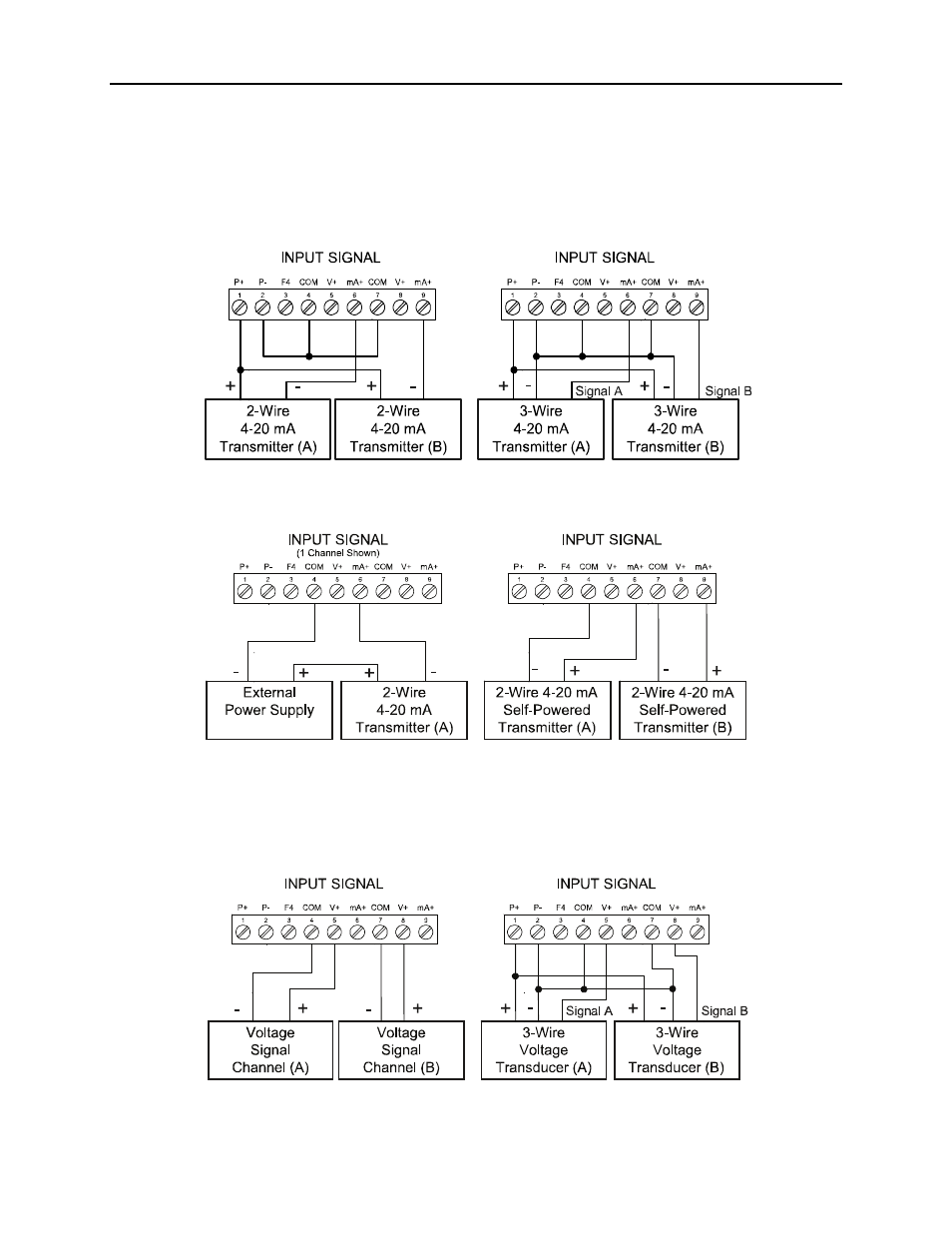
Analog Input Signal Connections
Analog input signal connections are made to a nine-terminal connector labeled SIGNAL on the back of
the scanner. The COM (common) terminals are the return for the 4-20 mA and the
±10 V input signals.
The two COM terminals connect to the same common return, and are not isolated.
Current and Voltage Connections
The following figures show examples of current and voltage connections. There are no switches or jumpers
to set up for current and voltage inputs. Setup and programming is performed through the front panel
buttons.
Figure 15. Transmitters Powered by Internal Supply
Figure 16. Transmitter Powered by Ext. Supply or Self-Powered
The current input is protected against current overload by a resettable fuse. The display may or may not
show a fault condition depending on the nature of the overload. The fuse limits the current to a safe level
when it detects a fault condition, and automatically resets itself when the fault condition is removed.
Figure 17. Voltage Input Connections
The scanner is capable of accepting any voltage from -10 VDC to +10 VDC.