Scsi test two, Stest2), Scsi test two (stest2) – Avago Technologies LSI53C895A User Manual
Page 199: Scsi test, Two (stest2), Register: 0x4e
SCSI Registers
4-91
R
Reserved
[5:4]
QEN
SCLK Quadrupler Enable
3
This bit, when set, powers up the internal clock
quadrupler circuit, which quadruples the SCLK 40 MHz
clock to an internal 160 MHz SCSI clock required for
Ultra SCSI and Ultra2 SCSI operation. When cleared, this
bit powers down the internal quadrupler circuit.
QSEL
SCLK Quadrupler Select
2
This bit, when set, selects the output of the internal clock
quadrupler for use as the internal SCSI clock. When
cleared, this bit selects the clock presented on SCLK for
use as the internal SCSI clock.
ISEL[1:0]
Interrupt Select
[1:0]
The LSI53C895A supports different interrupt routing
modes. These modes are described in the following table.
For additional information on the LSI53C895A interrupt
routing modes see
Section 2.2.17, “Interrupt Routing,”
in
Register: 0x4E
SCSI Test Two (STEST2)
Read/Write
SCE
SCSI Control Enable
7
Setting this bit allows assertion of all SCSI control and
data lines through the
SCSI Output Control Latch (SOCL)
and
registers regardless
of whether the LSI53C895A is configured as a target or
initiator.
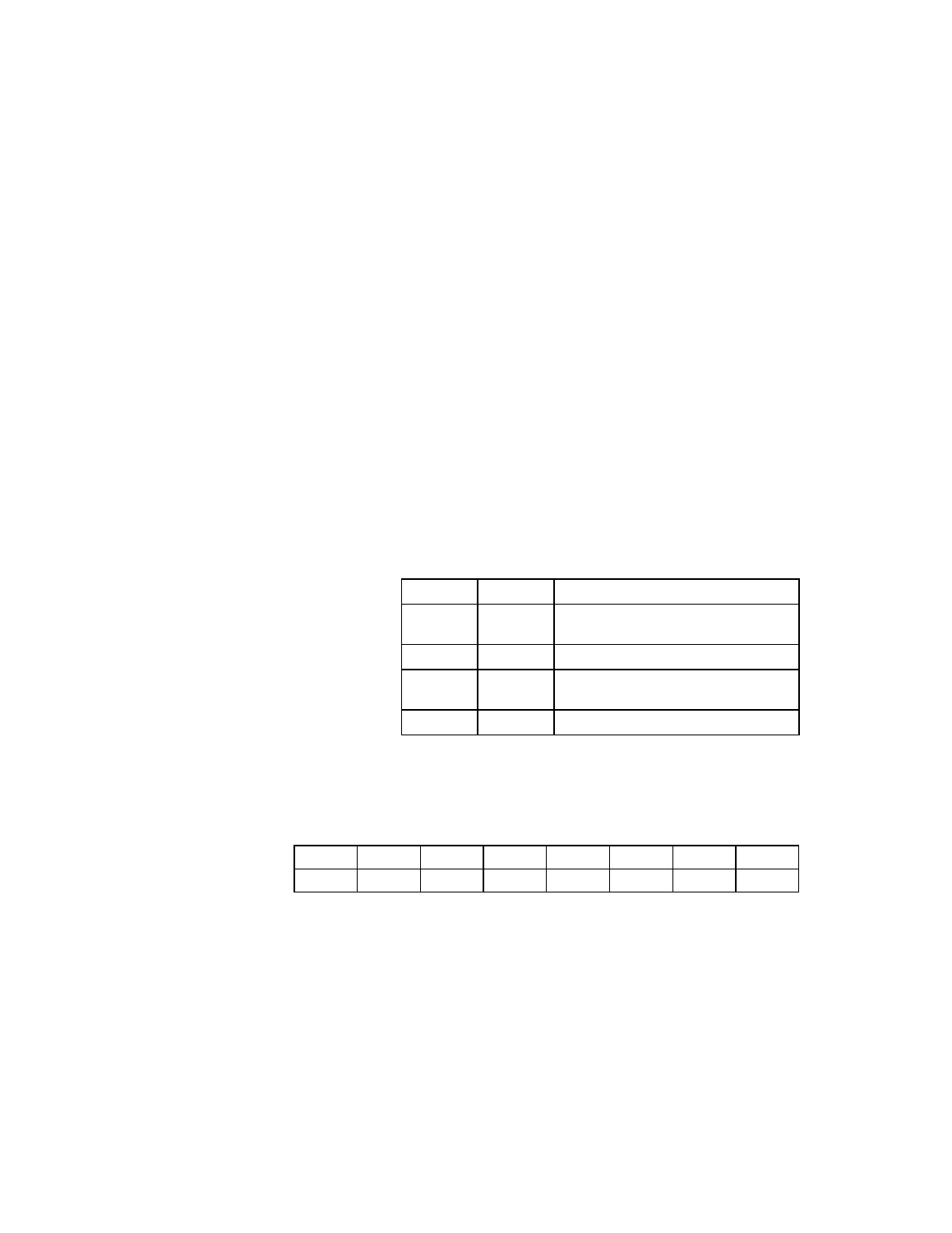
Mode
ISEL[1:0]
Interrupt Routing
0
00
Interrupts are signaled on IRQ/ and
ALT_IRQ/.
1
01
Interrupts are only signaled on IRQ/.
2
10
Interrupts are only signaled on
ALT_IRQ/.
3
11
Reserved.
7
6
5
4
3
2
1
0
SCE
ROF
DIF
SLB
SZM
AWS
EXT
LOW
0
0
0
0
0
0
0
0