Avago Technologies LSI53C895A User Manual
Page 266
6-6
Electrical Specifications
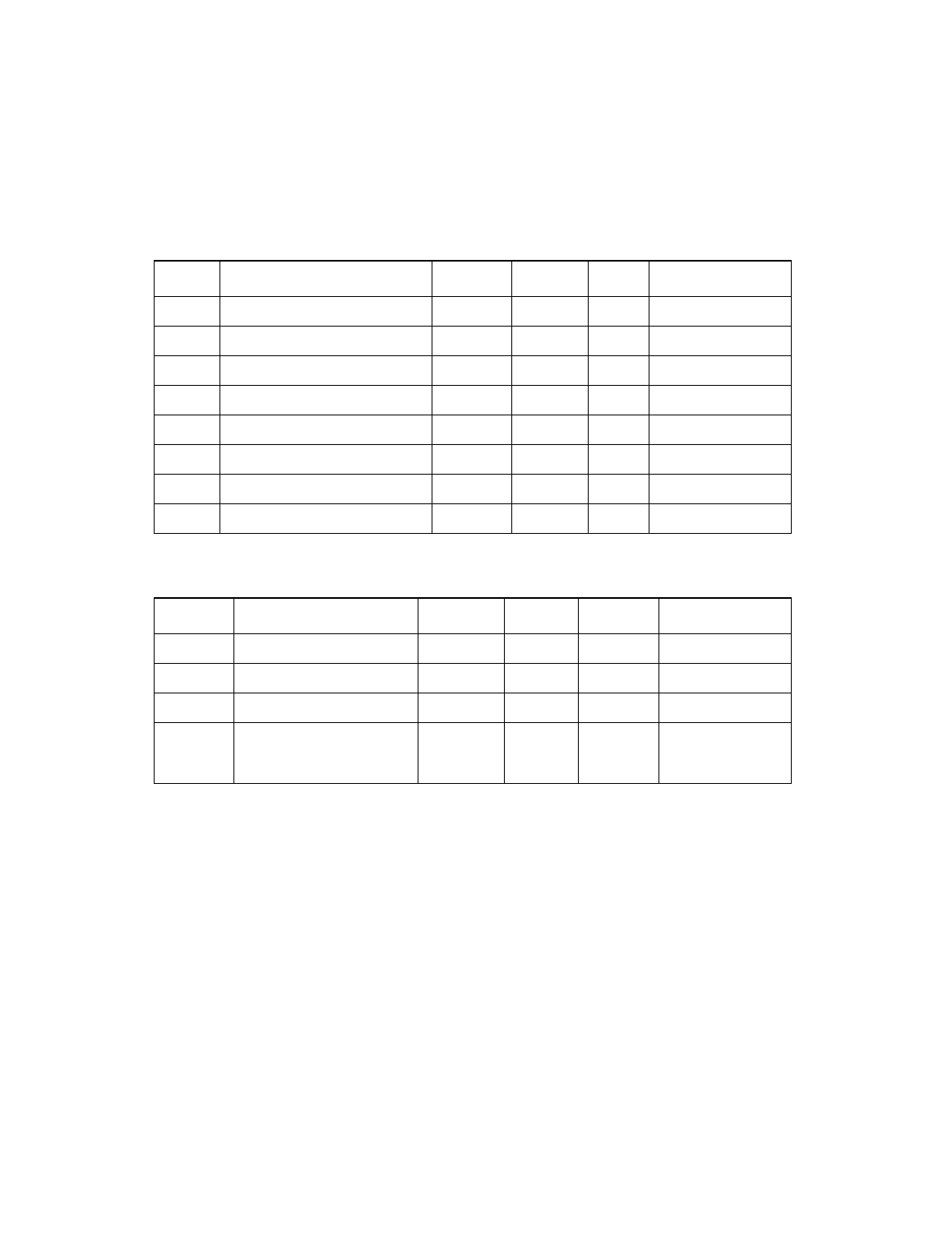
Table 6.9
Bidirectional Signals—AD[31:0], C_BE[3:0]/, FRAME/, IRDY/, TRDY/,
DEVSEL/, STOP/, PERR/, PAR
Symbol
Parameter
Min
Max
Unit
Test Conditions
V
IH
Input high voltage
0.5 V
DD
5.25
V
–
V
IL
Input low voltage
V
SS
−
0.3
0.3 V
DD
V
–
V
OH
Output high voltage
0.9 V
DD
–
V
−
500
µ
A
V
OL
Output low voltage
–
0.1 V
DD
V
1500
µ
A
V
OH
5 V tolerant output high voltage
2.4
–
V
−
16 mA
V
OL
5 V tolerant output low voltage
–
0.55
V
16 mA
I
OZ
3-state leakage
−
10
10
µ
A
V
PIN
= 0 V, 5.25 V
I
PULL
Pull-down current
7.5
75
µ
A
–
Table 6.10
Input Signals—CLK, GNT/, IDSEL, RST/, SCLK, TCK, TDI, TEST_HSC
1
,
TEST_RST, TMS, TRST/
1. TEST_HSC has a pull-down.
Symbol
Parameter
Min
Max
Unit
Test Conditions
V
IH
Input high voltage
0.5 V
DD
5.0
V
–
V
IL
Input low voltage
V
SS
−
0.3
0.3 V
DD
V
–
I
IN
Input leakage
2
2. The Input leakage test does not apply to the TEST_RST/ pin with V
PIN
= 0 V.
−
10
10
µ
A
V
PIN
= 0 V, 5.25 V
I
PULL-UP
3
3. Pull-up spec does not apply to: SCLK, CLK, GNT/, IDSEL, and RST/.
Pull-up current - only on
TCK, TDI, TEST_HSC,
TEST_RST, TMS, TRST/
−
75
−
7.5
µ
A
–