Initiator and target synchronous transfer – Avago Technologies LSI53C896 User Manual
Page 334
6-66
Specifications
Version 3.3
Copyright © 1998–2003 by LSI Logic Corporation. All rights reserved.
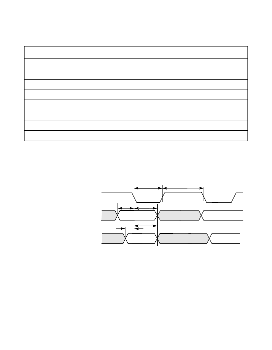
Figure 6.39 Initiator and Target Synchronous Transfer
Table 6.49
Ultra2 SCSI Transfers 40.0 Mbyte (8-Bit Transfers) or
80.0 Mbyte (16-Bit Transfers) Quadrupled 40 MHz Clock
1
1. Transfer period bits (bits [7:5] in the
register) are set to zero and the
Extra Clock Cycle of Data Setup bit (bit 7 in
) is set
.
Symbol
Parameter
2
2. During Ultra2 SCSI transfers, the value of the Extend REQ/ACK Filtering bit (
,
bit 1) has no effect.
Min
Max
Unit
t
1
Send SREQ/ or SACK/ assertion pulse width
8
–
ns
t
2
Send SREQ/ or SACK/ deassertion pulse width
8
–
ns
t
1
Receive SREQ/ or SACK/ assertion pulse width
6
–
ns
t
2
Receive SREQ/ or SACK/ deassertion pulse width
6
–
ns
t
3
Send data setup to SREQ/ or SACK/ asserted
10
–
ns
t
4
Send data hold from SREQ/ or SACK/ asserted
10
–
ns
t
5
Receive data setup to SREQ/ or SACK/ asserted
4.5
–
ns
t
6
Receive data hold from SREQ/ or SACK/ asserted
4.5
–
ns
Valid n
Valid n + 1
n + 1
n
t
1
t
2
t
3
t
4
SREQ/
Send Data
Receive Data
SDP[1:0]/
or SACK/
SD[15:0]/,
SDP[1:0]/
SD[15:0]/,
t
5
t
6
Valid n + 1
Valid n