Viewing profibus slave configuration – ProSoft Technology 5205-104S-PDPS User Manual
Page 85
Diagnostics and Troubleshooting
4205/5205-TS-104S-PDPS ♦ ProLinx Standalone
IEC-60870-5-104 to PDPS Communication Module with Time Stamp
ProSoft Technology, Inc.
Page 85 of 128
July 12, 2007
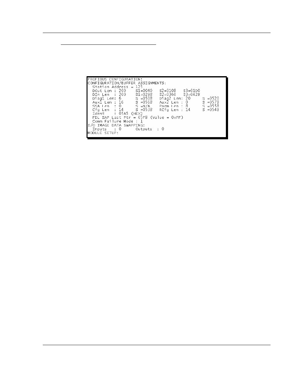
Viewing PROFIBUS Slave Configuration
The Configuration Screen displays many specific SPC3 ASIC diagnostic data
useful to ProSoft Technology Technical Support and advanced PROFIBUS
users. Additional information can be found in the SPC3 specification.
Station Address
= The configured station address set by the user
DOut Len
is the total number of output bytes with the S1, S2 and S3 values
being pointers to the 3 output buffers in the SPC3 chip.
DIn Len
is the total number of input bytes with the S1, S2 and S3 values being
pointers to the 3 input buffers in the SPC3 chip.
Diag1Len
should always be 6 to represent the minimal number of diagnostic
bytes and S= pointer in SPC3 chip to this data.
Diag2Len
is the extended diagnostic buffer length and S is a pointer to this data
in the SPC3 chip.
Aux1 Len:
(see SPC3 specification) and S is a pointer to this data in the SPC3
chip.
Aux2 Len:
(see SPC3 specification) and S is a pointer to this data in the SPC3
chip.
SSA Len
is not used and should be 0 and its pointer S is N/A.
Param Len
= is the length of the parameter data for the slave with S as the
pointer in the SPC3 chip to the data.
Cfg Len
is the configuration length for the slave with S as the pointer.
RCfg len
is that received from the master with S as the pointer.
Ident
is the PROFIBUS identification number for the module.
FDL SAP last PTR
is the end of all the PDPS data in the SPC3 chip. This value
must be less than 0xFF or there is a memory overflow problem!
Comm Failure mode
is that from the configuration file as is the swapping of
input and output data.