Super Systems 9120 with TS User Manual
Page 34
SSi 9120 Touchscreen Interface
4586 – 9120 With Touch Screen Interface
Page 34 of 80
screen. When it is over, the screen will display “idle” once again.
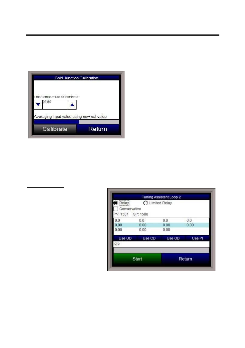
Cold Junction
The cold junction should be performed
after any zero/span calibration
. To
perform a cold junction, the corresponding
T/C wire will need to be setup on the inputs.
A specific temperature will need to be sourced
to the selected input. Return to the main
screen by pressing the Return button three
times to read the input’s PV value. Mark
down the displayed PV value and determine
the difference between the displayed PV value
and the value that is being sourced.
For example, assume that input 3 is setup for
T/C type K, and 1000 ◦F is being sourced in.
On the main display, the PV for input 3 is 1002 ◦F. Return to the
Cold Junction
menu under the
Calibration
menu. The value displayed on the
Cold Junction Calibration
screen is the current
temperature of the terminals. Assume this value is 95.5 ◦F. In the number box, the user would
enter a -2 degree difference, or 93.5 ◦F, since the temperature sourced (1000 ◦F) – PV value
(1002 ◦F) = -2 ◦F. Press the Calibrate button to finish off the cold junction calibration. Return to
the main screen to see if the selected input’s PV value is now displaying the correct value of what
is being sourced. If necessary, repeat these steps to further calibrate the cold junction value.
Tuning Assistant
The tuning assistant menu option will
allow the user to automatically
generate the PID loop settings for the
control loops in the 9120 controller.
The tuning assistant can be performed
on either Loop 1 or Loop 2.
Note - The four buttons at the bottom
of the screen: Use UD, Use CD, Use
OD, and Use PI will be inaccessible
until some PID settings are loaded into
the PID settings list above the buttons
.
The user can select the tuning option
from the top left of the screen. The
choices are: Relay and Limited
Relay. This option will allow the user
to limit the output value while the
controller is controlling the furnace. Normal operation will typically use 100 % output. When the
limited relay option is selected, the “Tuning Delta:” label and an edit box will be displayed. When
the Relay option is selected, the “Tuning Delta:” label and the edit box will be hidden. The
“Tuning Delta” value will be the amount to limit the controller by. Pressing the edit box will
display the numeric keypad, which will allow the user to enter the limiting value.