Super Systems 9120 with TS User Manual
Page 60
SSi 9120 Touchscreen Interface
4586 – 9120 With Touch Screen Interface
Page 60 of 80
hysteresis of 8 ◦F, the alarm and pump will turn off at 202 ◦F. It will turn back on when it is 10
◦F above setpoint. If the setpoint is still 200 ◦F, then at 210 ◦F, it will turn on again.
Clicking on this value will display an input box from which the user can select a new value. The
range is from 0 to 9999.
Smart Alarm
This value is a display of the Smart Alarm status. A smart alarm is an alarm that works with a
Process Variable (PV), and, when enabled, it will not be active until the PV is within band of the
setpoint. The alarm sounding - if active - will be disabled until within the SP band. When it is in
band, the alarm will go active unless on delay time is set.
Example: If the SP is 1700 and the band is 10 degrees the alarm will not be active until the PV
reaches 1690. The value can be either disabled or enabled.
ON Delay Time
This value is the ON Delay Time. Clicking on this value will display an input box from which the
user can select a new value. The range is from 0 to 9999.
0 SP Blocks Alarm
This value will allow a 0 setpoint to block an alarm. The options are either no or yes.
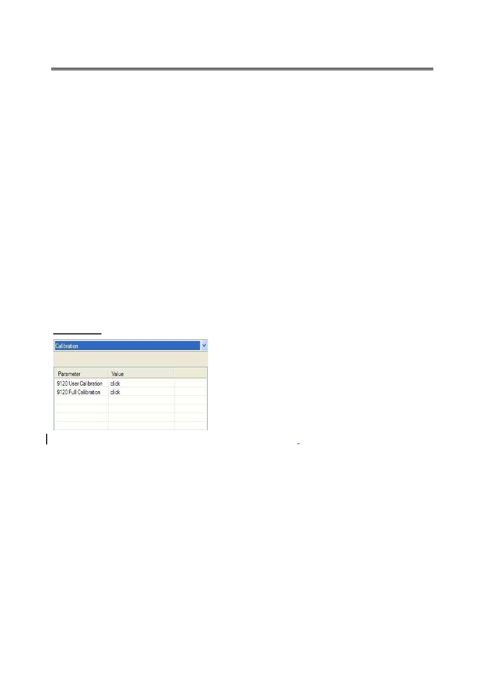
Calibration
Overview
The 9120 can be calibrated using the operator interface
Configurator software usually supplied with the system.
Before performing this procedure on a newly installed
controller, the unit needs to be powered on for at least
30 minutes for a warm up period.
The 9120 has three analog inputs. Each range has a
zero and span calibration value. A cold junction trim
value must be calibrated for thermocouple inputs.
There are two analog outputs each with a zero and span value.
The cold junction trim value
must be performed, if necessary, after the zero and span calibration
.
Equipment needed
A certified calibrator(s) with the ability to input and read millivolts, milliamps and thermocouples
is required. The appropriate connection leads are also required. A 24VDC 75-watt power supply is
required. The operator interface method requires a PC with the Configurator software loaded. An
Ethernet crossover cable is required. It is important to note that when performing a zero or span
calibration,
do not use
regular thermocouple wiring. Instead, use any kind of regular sensor
wire, or even regular copper wire. To perform the calibrations, the user will need a calibrator
that is capable of sourcing volts, millivolts, and temperature.
Notes
Input 1 – terminals 31 and 32
Input 2 – terminals 29 and 30