Super Systems 9120 with TS User Manual
Page 25
SSi 9120 Touchscreen Interface
4586 – 9120 With Touch Screen Interface
Page 25 of 80
The input offset value is algebraically added to the input value to adjust the input curve on read-
out.
Note - The input offsets are unscaled
. The range is –32767 to 32767.
Trip Point 1 Setpoint
This is the trip point 1 setpoint value. The range is –32767 to 32767.
Trip Point 1 Force Value
This is the trip point 1 force value. The range is –32767 to 32767.
Trip Point 1 Direction
This is the trip point 1 direction. The options are: input above setpoint or input below
setpoint.
Trip Point 2 Setpoint
This is the trip point 2 setpoint value. The range is –32767 to 32767.
Trip Point 2 Force Value
This is the trip point 2 force value. The range is –32767 to 32767.
Trip Point 2 Direction
This is the trip point 2 direction. The options are: input above setpoint or input below
setpoint.
High Input Limit Setpoint
This is the setpoint for the high input limit. The range for this can be –32767 to 32767.
High Input Limit Hysteresis
This is the hysteresis for the high input limit. The range for this can be –32767 to 32767.
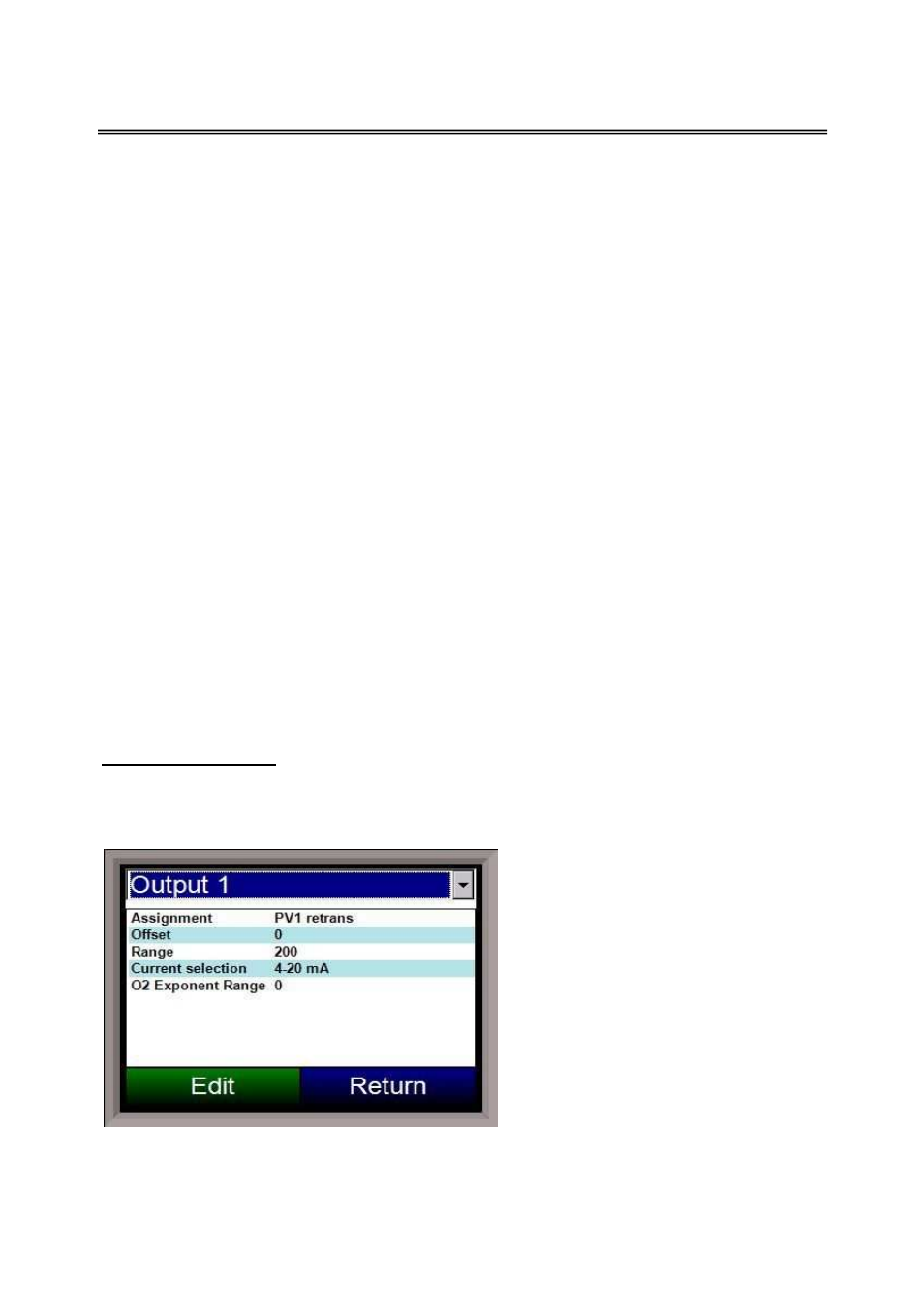
Analog Output Setup
The 9120 controller has the option of two analog outputs. The outputs are ranged for a 4 – 20
milliamp signal or a 0 – 20 milliamp signal. Each output comes with a factory default
configuration dependent on the application. Each output can be modified prior to shipment to
your facility or in the field by a supervisor.
Analog Output Terminals:
Analog output 1 – terminals 24 and 25
Analog output 2 – terminals 25 and 26
Assignment
The analog output assignment can be
modified depending on your system
requirements. To change the Assignment,
first select which analog output you want
to change by selecting it in the pull-down
menu. Select the desired assignment
from the list and click OK. The following
is a list of the options: