Super Systems 9120 with TS User Manual
Page 17
SSi 9120 Touchscreen Interface
4586 – 9120 With Touch Screen Interface
Page 17 of 80
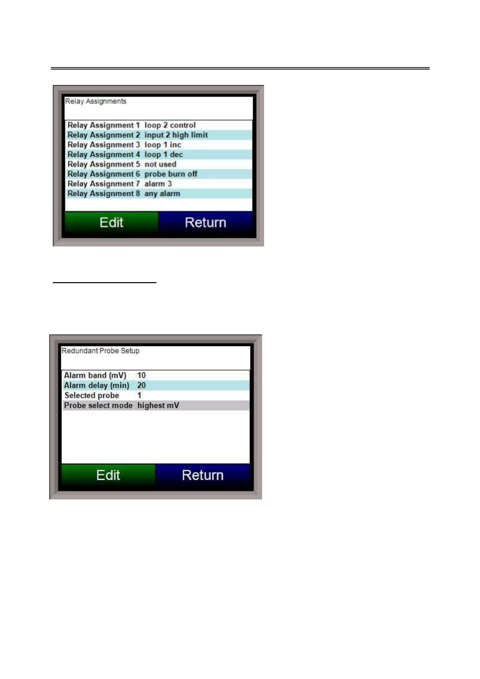
This screen will display a description of
the eight relay assignments. The eight
“Outputs” on the front of the unit
represent the eight relay assignments,
where Output #1 = Relay Assignment 1,
etc. Most of the relay assignments are
fixed in the unit. Relay 1 is the loop 2
control relay. Relay 2 is the input 2 high
limit relay. Relay 3 is the loop 1
increase relay. Relay 4 is the loop 1
decrease relay. Relay 6 is the probe
burnoff relay. Relay 8 is the any alarm
relay. Relay 7 is the only relay that can
be assigned.
Redundant Probe Setup
This menu option will allow the user to configure the 9120 for RPS functionality.
Alarm band (mV)
This is the millivolt difference that must be observed for the RPS to change probes. For example,
when the RPS is selecting the highest
probe with probe 1 as 1055 mV and a
band of 20 mV, and if probe 2 hits 1076
mV, the RPS will start counting down the
Alarm Delay timer (below). When the
delay times out, probe 2 would be
selected. If probe 2 comes back in band
(drops to 1075), the timers starts over
again. The range is 0 to 600.
Alarm delay (min)
This is the number of minutes that the
RPS waits to switch probes when an out-
of-band condition is detected.
Note -
There is a 950 mV low limit for an alarm.
This condition is typically found during a
burnoff, so the alarm will not be active
when the input drops below 950 mV
.
The range is 0 to 9999.
Selected Probe
Indicates which probe is selected.
Note – This field is only editable when the Probe select mode
(below) is set to no auto switch
. The options are: 0 or 1.
Note – The number of the probe is 0-
based, so “0” = probe 1 and “1” = probe 2
.