Super Systems 9120 with TS User Manual
Page 64
SSi 9120 Touchscreen Interface
4586 – 9120 With Touch Screen Interface
Page 64 of 80
This field provides an offset for the starting point for PID control, also referred to as “Load Line”
or “Manual Reset”.
The range is –100 to 100.
High Limit
This is the high limit value. The range is –100 to 100.
Low Limit
This is the low limit value. The range is –100 to 100.
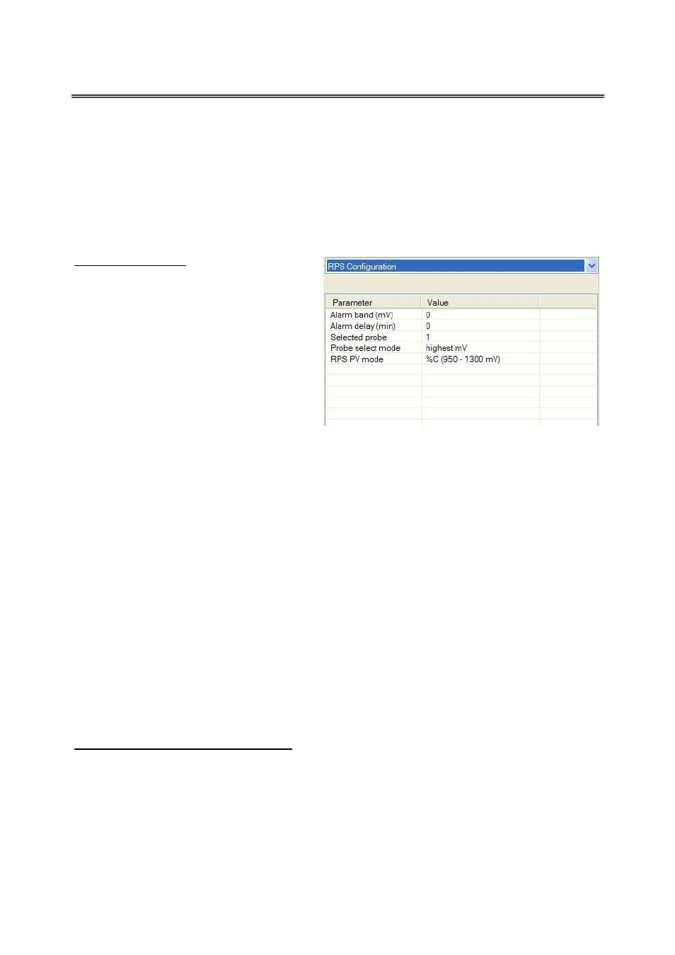
RPS Configuration
This menu option will allow the user to
configure the 9120 for RPS functionality.
Alarm band (mV)
This is the millivolt difference that must be
observed for the RPS to change probes. For
example, when the RPS is selecting the
highest probe with probe 1 as 1055 mV and
a band of 20 mV, and if probe 2 hits 1076
mV, the RPS will start counting down the
Alarm Delay timer (below). When the delay
times out, probe 2 would be selected. If probe 2 comes back in band (drops to 1075), the timers
starts over again. The range is 0 to 600.
Alarm delay (min)
This is the number of minutes that the RPS waits to switch probes when an out-of-band condition
is detected.
Note - There is a 950 mV low limit for an alarm. This condition is typically found
during a burnoff, so the alarm will not be active when the input drops below 950 mV
.
The range is 0 to 9999.
Selected Probe
Indicates which probe is selected.
Note – This field is only editable when the Probe select mode
(below) is set to no auto switch
. The options are: Probe 1 or Probe 2.
Probe select mode
This determines how the specified probe is selected. The options are: highest mV, lowest mV,
or no auto switch (manual mode).
RPS PV Mode
This will allow the user to select the PV mode for the RPS. The options are: %C (950 – 1300
mV), %O2 (0 – 600 mV), or mV (0 – 1300 mV).
Aux Input Module Offset Correction