Fms-bos – Wavecom W61PC V7.5.0 User Manual
Page 163
WAVECOM Decoder W61PC/LAN Manual V7.5
Transmission Modes
153
bottom of the first column (left) to the top of the last column (right) covering a matrix of 7 columns x 14
lines. Pixels are always sent in pairs.
Parameter
Value
Frequency range
HF
Operation modes
Graphic Mode, Broadcast/simplex
Modulation
FSK
Symbol rate
122.5 Bd
Receiver settings
DATA, CW, LSB or USB
Input format(s)
AF, IF
By selecting the mode with a baud rate of 122.5 Bd, reception is started. Selecting Polarity will determine
normal or inverse screen color.
FMS-BOS
FMS-BOS is a radio signaling system for security authorities and organizations. The system allows for a
major reduction in message interchange between mobile units and a control center by digital transmission
of abbreviated telegrams.
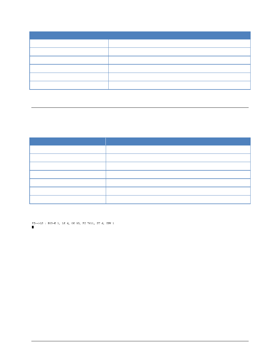
Parameter
Value
Frequency range
VHF
Operation modes
Simplex
Modulation
FM, SUB FSK
Symbol rate
1200 Bd
Receiver settings
FM, BW = 12 kHz
Input format(s)
AF, IF
Additional Info
BCD-Code with block coding
FMS-BOS operates at 1200 bit/s using FSK modulation of 1200 Hz and 1800 Hz tones.
FMS-BOS Transmission Example
The FMS-BOS data telegrams always have the same structure and a length of 48 bits regardless of the
transmission direction or message contents. The actual information is contained in 40 bits. The BCD code
is used to transmit the digits in the telegram.
A FMS-BOS message is preceded by 12 bits of carrier and a sync character (0x1a).
The message itself consists of 10 BCD blocks.
Block 1 is the BOS service identifier (0...f) identifying the service issuing the message.
Block 2 is the state identifier (0...f) identifying the German state. Due to the fact that the number of
states exceeds the number of available identifier digits, digits E and F are additionally identified by the lo-
cation identifier to be used by two states each.
Blocks 3 - 4 are the location identifier (e.g. OK 10) and can assume one of 99 different possibilities. The
actual value is determined by each individual state.
Blocks 5 – 8 are the vehicle identifier (e.g. 4213) and can contain one of 9999 combinations. The indi-
vidual identifiers are assigned by each specific service.
Block 9 is the status field contains the actual information. 16 different messages may be transmitted. De-
pending on the R direction bit status messages attain different meanings. Furthermore the actual meaning
of a status message is determined by the service and the individual states.