Psk-31, psk-63, psk-125, psk-250 – Wavecom W61PC V7.5.0 User Manual
Page 213
WAVECOM Decoder W61PC/LAN Manual V7.5
Transmission Modes
203
PSK-31, PSK-63, PSK-125, PSK-250
PSK-31 is a very narrow-band and reliable mode. The good performance against disturbances is achieved
by the use of DPSK modulation. Two demodulators are available:
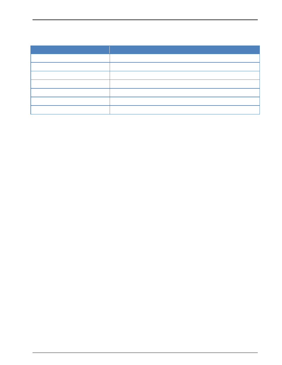
Parameter
Value
Frequency range
HF
Operation modes
Simplex
Modulation
DBPSK, DQPSK
Symbol rate
31.25, 62.5, 125 or 250 Bd
Receiver settings
DATA, CW, LSB or USB
Input format(s)
AF, IF
Additional Info
3.580 MHz, 7.035 MHz, 14.070 MHz
For normal use, DBPSK can be selected to demodulate a bi-phase modulated signal. The baud rate
is fixed at 31.25, 62.5, 125 or 250 Bd and is optimized to transfer data at the keyboard input-rate
of an average operator.
Alternatively DQPSK can be selected to demodulate a four-phase modulated signal. In this mode
additional redundancy is generated by a convolutional encoder with a code rate = 1/2 and a con-
straint length of K=5, i.e. 2 bits were produced per bit by 2 polynomials. After the demodulation of
the signal, the encoded bits are converted to a normal bit stream by a Viterbi decoder with K=5
and a code rate =1/2.
To separate the transferred characters, two zeros are inserted between every character. Thus the charac-
ters can be clearly separated, as long as no two consecutive zeros appear in the character itself. This was
taken into consideration when designing the alphabet.
To optimize the data throughput rate of the system, an alphabet with a variable character length is used.
For frequently used characters a symbol is used, which has a short word length (as is done with the Huff-
man compression). This alphabet is called Varicode.
PSK-63 and higher speeds are used in amateur-radio emergency-networks for information-transfer with
the FLARQ-protocol. The decoders for these modes can interpret FLARQ messages.
Tuning a PSK-31, PSK-63, PSK-125, PSK-250 Signal
After launching the mode, the first step is to look for a valid PSK-31 signal in the spectrum. Usually a
number of stations are working within the PSK segment which covers a few kHz.
The bandwidth of the spectrum can be switched between 500 Hz, 1000 Hz, 4000 Hz and 24000 Hz. After
that the lower limit of the signal may be selected with the left cursor and the upper boundary with the
right cursor. Using the center cursor, the center frequency may be more precisely set. The accurate ad-
justment of the center frequency is very important and directly influences the performance of
the decoding.
To ensure, that the system can handle drifting signals or a coarsely adjusted center frequency, AFC may
be enabled in the Demodulator menu. The carrier tracking function is now activated. If the deviation be-
tween the tracked and the adjusted center frequency is too large, the center frequency should be correct-
ed. Carrier tracking only works over a range of:
DBPSK center frequency ± 8 Hz
DQPSK center frequency ± 4 Hz
Hence adjustment of the center frequency must be accurate.
The tuning display indicates if a DBPSK or a DQPSK signal is being received. Two bars mean DBPSK, four
bars DQPSK. The demodulator must be adjusted accordingly.
Polarity of PSK-31, PSK-63, PSK-125, PSK-250
If a LSB signal is received using the receivers USB position or vice versa, the phase-plane is mirrored on
the horizontal axis. For a DBPSK signal this has no effect, because all the phase states are on the horizon-
tal axis itself. For DQPSK however this must be considered by switching the polarity. This can be done in