Vdew, Vdl-m2 – Wavecom W61PC V7.5.0 User Manual
Page 245
WAVECOM Decoder W61PC/LAN Manual V7.5
Transmission Modes
235
The preferred demodulator type is the MFSK mode: Otherwise the DSP mode may be enabled in the De-
modulator menu using the Mode item.
The proper assignment of the V1 and V2 keying combinations must now be set-up using the Y-B V1 Chan-
nel and Y-B V2 Channel items in the Options menu.
Most stations use the Y-Y-B-B setting for the V1 channel. The second channel frequently uses either the Y-
B-Y-B or B-Y-B-Y combination.
If synchronization is not achieved after configuration has been completed, change the V1 and V2 settings
until the right combination has been found. For example, transmissions are possible with V1 set to B-Y-B-
Y and V2 set to Y-B-B-Y. This combination results in the first three telegraph characters to be transmitted
on the V2 channel.
TWINPLEX stations only key the two inner frequencies f2 and f3 during the IDLE state (no traffic) or dur-
ing the RQ state (incorrect acknowledgement from the remote station). In these states SITOR and
TWINPLEX systems cannot be distinguished from each other.
VDEW
The entire call number is transmitted by consecutive tones in decade sequence. When two identical digits
are to be transmitted consecutively, then an eleventh frequency is used as a repetition identifier.
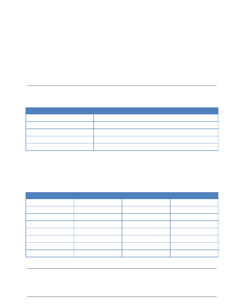
Parameter
Value
Frequency range
VHF/UHF
Operation modes
Analogue Selcal
Modulation
FM, SUB tone
Receiver settings
FM, BW = 12 kHz
Input format(s)
AF, IF
If more than two identical digits are to be transmitted, the repetition tone is appended to the digit tone
(e.g. 22222 is transmitted as f2 fw f2 fw f2, where f2 is the tone for "2" and fw is the repetition tone).
In most systems the accuracy of the single frequencies has to be within +1/-1.5% of the nominal value.
Decoding the selective calls is started by clicking on a system. If transmission and system selection con-
form, the call sign is displayed on the monitor. In the Options menu a Time stamp function can be ena-
bled to add date and time to each call.
Tone Allocation
Digit
Hz
Digit
Hz
0
2280
8
1520
1
370
9
1860
2
450
A
2000
3
550
B
2100
4
675
C
2200
5
825
D
2300
6
1010
E
2400
7
1240
Tone duration: 100 ms
VDL-M2
VHF digital link (VDL) Mode 2 is an air-ground data link specified in the ICAO documents “Annex 10 Vol-
ume III - Communication Systems” and” Manual on VHF Digital Link (VDL) Mode 2”.