Fft hf, fft sub, fft dir, fft sat, Tuning fft or sonagram, Tuning fsk signals – Wavecom W61PC V7.5.0 User Manual
Page 78: Tuning mfsk signals
68
Analysis Tools
WAVECOM Decoder W61PC/LAN Manual V7.5
calculated as the IF output frequency (455 kHz) minus half of the selected FFT bandwidth (24/2 kHz) =
Offset (443 kHz). The measurement range is now 443 kHz - 467 kHz.
For the 455 kHz receiver IF output of a shortwave receiver (e.g. HF-1000), the offset frequency is first ad-
justed to 453.3 kHz to obtain the standard center frequency of 1,700 Hz. The HF-1000 BFO must now be
adjusted to 1,700 Hz.
FFT HF, FFT SUB, FFT DIR, FFT SAT
FFT Type
Start Frequency
End Freqeuncy
FFT HF
Offset Frequency
Bandwidth
FFT SUB
Offset Frequency
Bandwidth
FFT DIR
Offset Frequency – Bandwidth/2
Offset Frequency + Bandwidth/2
FFT SAT
Offset Frequency – Bandwidth/2
Offset Frequency + Bandwidth/2
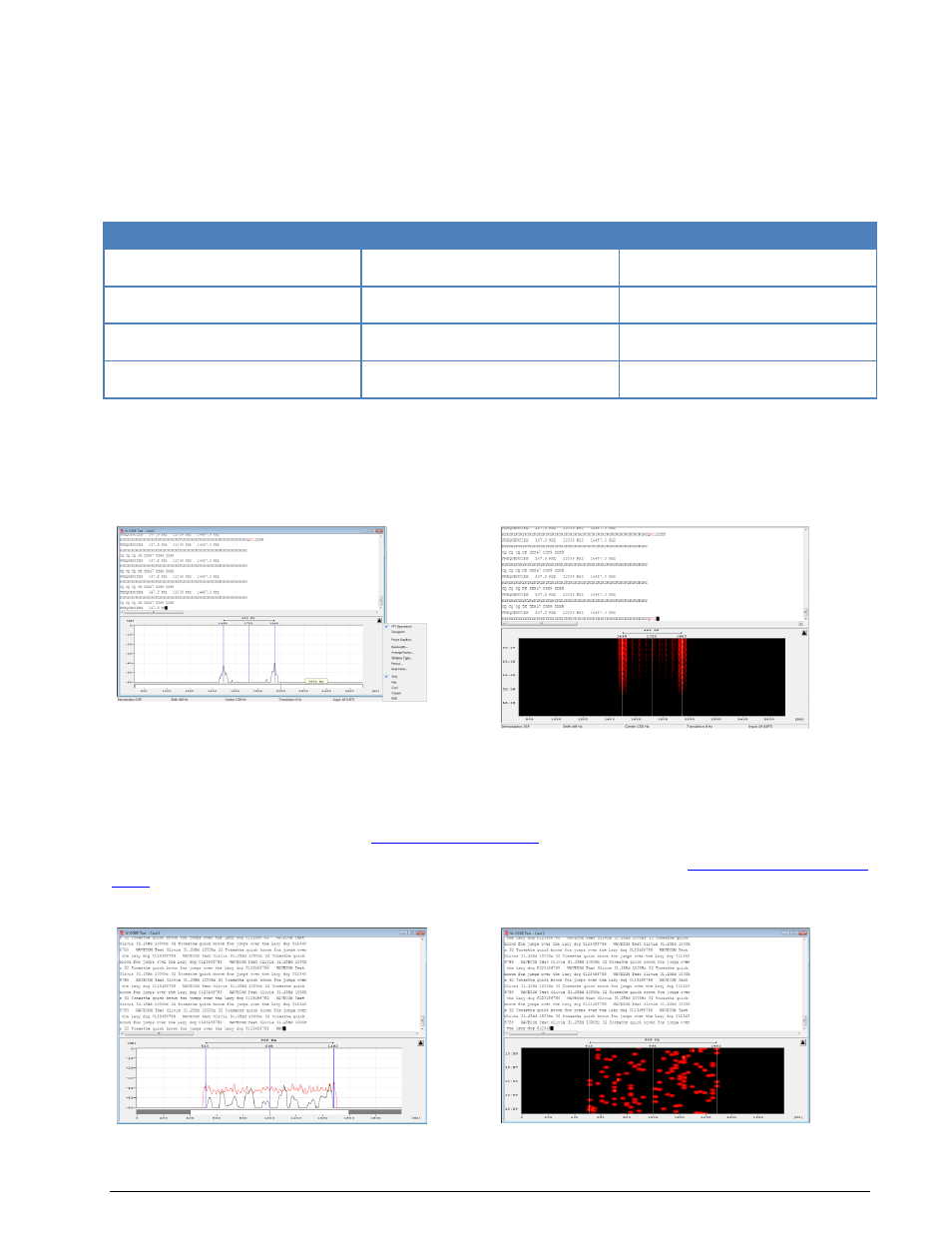
Tuning FFT or Sonagram
In some modes a Tuning FFT or Sonagram is available. The FFT or Sonagram can be used to set the
center frequency, shift, and passband filter.
Tuning FSK Signals
Mark and Space are selected with the right and left cursor. The precision of the center frequency is
very important and directly influences the performance of the decoder.
After every change, the center frequency and shift are automatically updated.
Automatic tuning is also available. It works perfectly as long as there is only one input signal present in
the spectrum. To apply a filter, see “
” on page 65.
Options can be set using the right mouse button or the context menu (see “
” on page 59). It is possible to remove the tuning FFT or Sonagram in the View Menu.
Tuning MFSK Signals