Wavecom W61PC V7.5.0 User Manual
Page 266
256
Classifier (Optional)
WAVECOM Decoder W61PC/LAN Manual V7.5
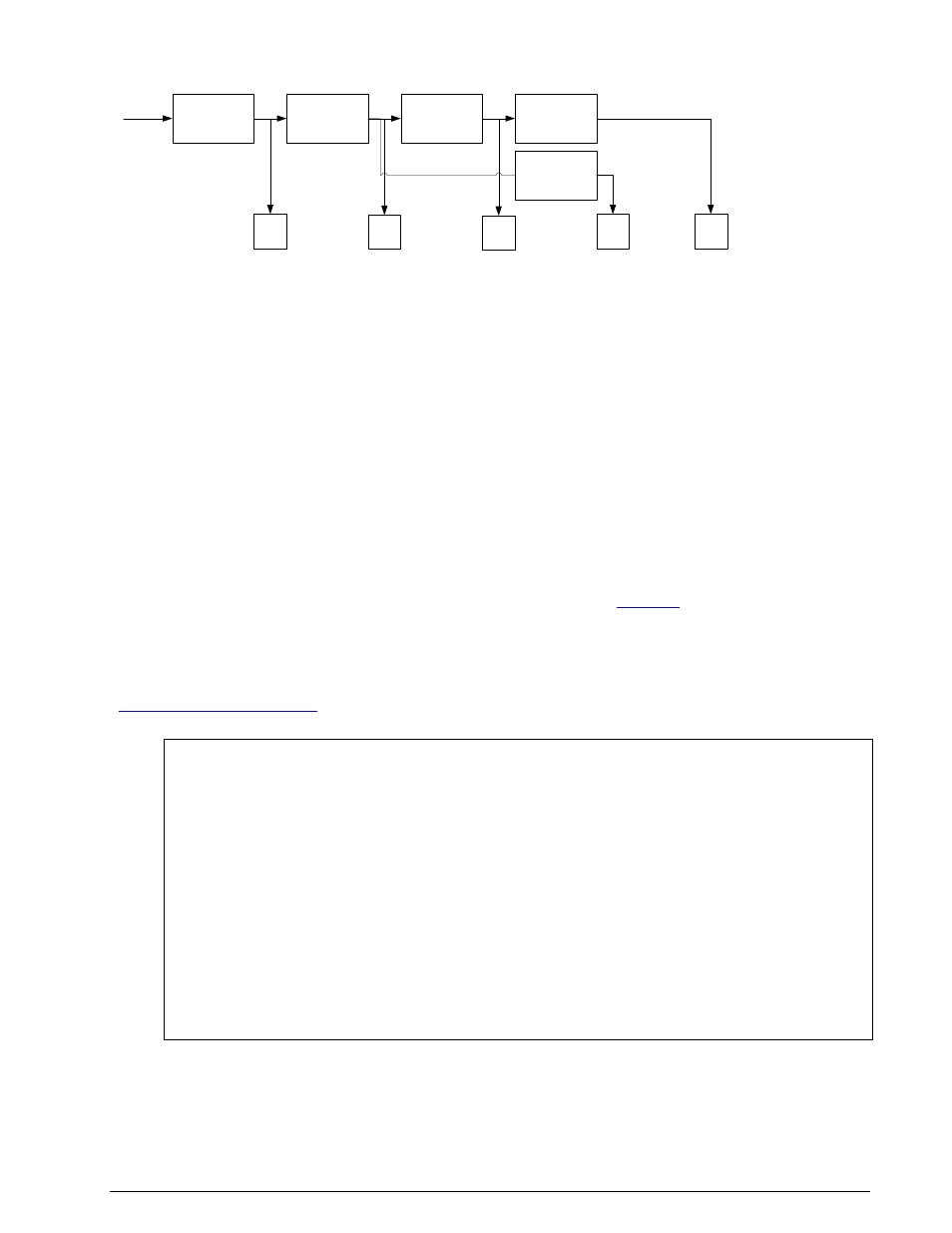
The possible signal paths of the CCC are shown below.
Classifer
XML Table Check
Code Check
Decoder
P1
P2
P3
P4
P5
Decoder
The classifier attempts to classify the input signals according to their modulation formats.
The table check will check the signal against the entries of an XML-formatted table.
The code check will check by attempting synchronization.
Finally the signal may be forwarded to a decoder for output.
The operation of the CCC is explained in detail below.
Classifier
Signal classification is done by providing the classifier with a sample of the complex values of the input
signal across the chosen sampling bandwidth for a chosen sampling time and a chosen sampling rate. This
sample is examined for the properties of the signals it contains. The results of the classification are output
as a list of classified signal parameters. The wideband classifier is able to recognize a double-modulated
signal. In such a case, the type of the outer modulation (e.g. AM, FM) is displayed within parentheses
along with the center frequency of the inner signal.
Two classification modes are provided: a manual mode and a continuous mode. In manual mode, the clas-
sifier will make one attempt at classification. In continuous mode, the classifier cyclically classifies signals
with a user selectable interval.
For more details on the operation of the classifier, refer to the section “
” on page 244.
XML Table Check
The objective of the table check is to accelerate the determination of the mode or protocol used by the
signal(s) under investigation. The signal parameters are checked against entries in a table in XML format.
The file containing the table may be created and edited by the user using CCC Editor (see the section
“
” on page 261). Below is a browser excerpt from the XML file with the begin-
ning of the file and entries for two modes, ACARS and ATIS displayed.
<?xml version="1.0" encoding="UTF-8" standalone="yes" ?>
-<SignalDatabase>
-<SignalList>
-<Signal Name="ACARS" Mode="acars" Modulation="FSK" Disabled="0">
<Baudrate>2400</Baudrate>
<NumTones>2</NumTones>
<CodecheckCounter>3</CodecheckCounter>
</Signal>
-<Signal Name="ATIS" Mode="atis" Modulation="FSK" Disabled="0">
<Baudrate>1200</Baudrate>
<NumTones>2</NumTones>
<CodecheckCounter>3</CodecheckCounter>
</Signal>
Code Check
Code check tests whether a candidate mode can successfully synchronize to the input signal for a required
number of times as specified in the corresponding entry in the XML file (<CodecheckCounter>).