Stanag-4539 – Wavecom W61PC V7.5.0 User Manual
Page 238
228
Transmission Modes
WAVECOM Decoder W61PC/LAN Manual V7.5
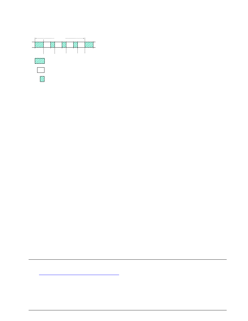
The 176 symbol data probe segment immediately follows a next frame beginning with the same 80 symbol
preamble. This repeated frame structure allows synchronization of the demodulator at any time of trans-
mission.
At the end of transmission, an EOM bit pattern (4B65A5B2, in hexadecimal notation, MSB first) is sent to
mark the end of message. The EOM sequence is followed by flush bits, to flush the FEC coder and to com-
plete the transmission of the remainder of the interleaver data block.
In most cases FEC and interleaving is used to combat the effects of fading, frequency shift, multipath, and
burst noise. User data is in this case first FEC encoded, interleaved, then mapped into PSK symbols and
transmitted in 32 symbol data segments. The 16 symbol channel probe segment transmitted between
each succeeding data segment has a known PSK pattern. Its purpose is to keep the demodulator, mainly
the equalizer, on track in spite of adverse propagation conditions during the HF transmission.
Generally STANAG-4529 transmits the user data in transparent binary mode. This should be defined by
the higher layer using the STANAG 4529 mode. For this reason the decoder displays the user data in BI-
NARY, HEX, ASCII ASYNC, ASCII ASYNC (7 Data bits and No Stop bit) or ASCII SYNC format selected from
Options | Message Type.... The decoder stops displaying data after the EOM bit pattern is received.
In the HEX display mode, the decoded binary data is just displayed as it is, MSB first.
In ASCII ASYNC mode, the bit stream is correlated with an ASCII ASYNC structure, i.e. one start-bit (0), 8
data bits and at least one stop bit (1). The 8 data bits are displayed LSB first. In addition to the EOM pat-
tern, the display will stop if more than 300 NULL characters are received or if the asynchronous data
structure is violated more than 80 times.
In ASCII ASYNC (7 data bits and no stop bit) mode, the bit stream is correlated with another ASYNC struc-
ture, i.e. one start bit (0) and 7 data bits. The 7 data bits are displayed LSB first. In addition to the EOM
pattern, the display will stop if more than 300 NULL characters are received.
In ASCII SYNC mode, each 8 bits (LSB first) represent one ASCII character. The display will stop if the
EOM pattern is received or if more than 20 NULL characters are received.
Tuning the decoder
The decoder can process signals in both SSB settings: USB and LSB. The sideband is selected by toggling
the polarity field of the display: NOR means USB and INV means LSB.
The center frequency of the decoder is set to the default value of 1700 Hz, but can be adjusted within a
range from 800Hz to 2400Hz. Small frequency deviations are automatically tracked and compensated dur-
ing the decoding. By using the bar graph, any remaining frequency difference can be compensated by fi-
ne-tuning of the receiver frequency or by adjusting the center frequency of the decoder.
Using the Frame Format field, the decoder can be set to one of the above listed user data configurations.
A correct coded frame format is determined by a confidence value being stable and greater than 95 (i.e.
95% correct), while for uncoded formats the value has no meaning and remains stable at 75.
STANAG-4539
See “
MIL-188-110B (Appendix C), STANAG 4539
” on page 171.
16
16
16
32
32
32
32
80
80
Block 1
Block 2
Block 3
Block 4
T = 213.33 ms
80
16
32
Preamble symbols
Data symbols
Channel probe symbols
Preamble