Configuring fip snooping, Overview, Fip snooping network diagram – H3C Technologies H3C S10500 Series Switches User Manual
Page 114
103
Configuring FIP snooping
Overview
To communicate with devices in the FC SAN, a node must register with an FC fabric. An FCF switch has
point-to-point connections with nodes. An FCF switch brings up an interface connected to a node only
after the node completes fabric login on the interface.
In an FCoE implementation, Transit switches can be present between ENodes and FCF switches, so the
connections between ENodes and FCF switches are no longer point-to-point. In this case, a node that has
not performed fabric login might communicate with the FC SAN. For example, two ENodes are
connected to one FCF switch through a Transit switch. After one ENode has registered with the FCF
switch and the corresponding interface is brought up, the other ENode can also communicate with the
FC SAN.
FCoE Initialization Protocol Snooping (FIP snooping) is a security feature that can run only on Transit
switches in an FCoE network. By checking source MAC addresses of FCoE frames, FIP snooping enables
a Transit switch to forward FCoE frames only between the following elements:
•
An ENode that has performed fabric login.
•
The FCF switch that has accepted its fabric login.
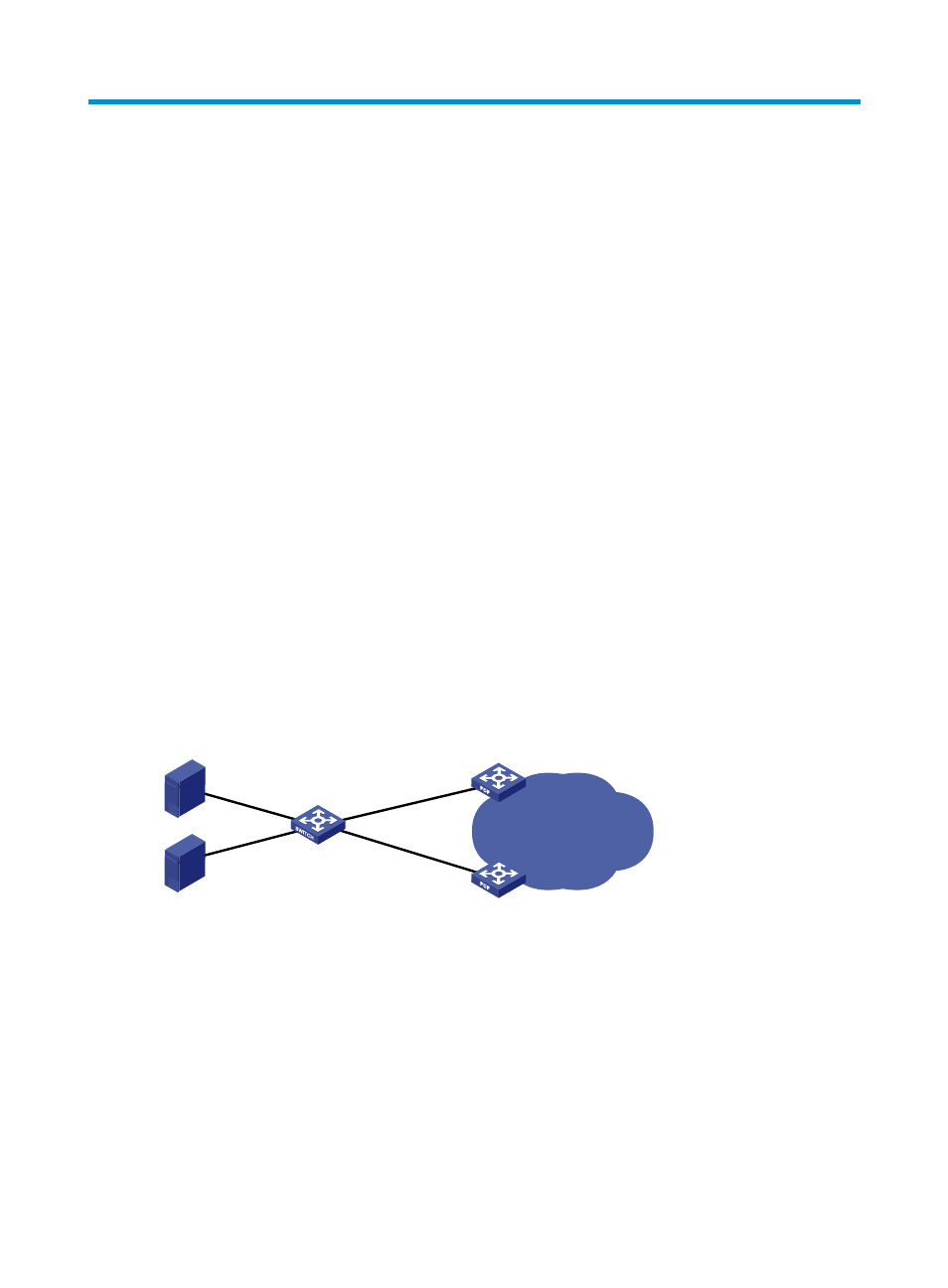
FIP snooping network diagram
shows a typical FIP snooping network diagram.
Figure 30 Network diagram
Ethernet interfaces on a Transit switch can operate in ENode or FCF mode. An Ethernet interface
connected to an ENode must be configured to operate in ENode mode. An Ethernet interface connected
to an FCF switch must be configured to operate in FCF mode.
To control packet exchange between ENodes and FCF switches, perform the following tasks:
•
Enable FIP snooping.
•
Configure the Ethernet interfaces to operate in a correct mode on the Transit switch.
FCF
mode
ENode
mode
ENode
mode
FCF switch
Transit switch
Fabric
ENode
FCF switch
FCF
mode