Basic concepts, Vfc interface and vn interface, Fip protocol – H3C Technologies H3C S10500 Series Switches User Manual
Page 17: Fcoe frames
6
•
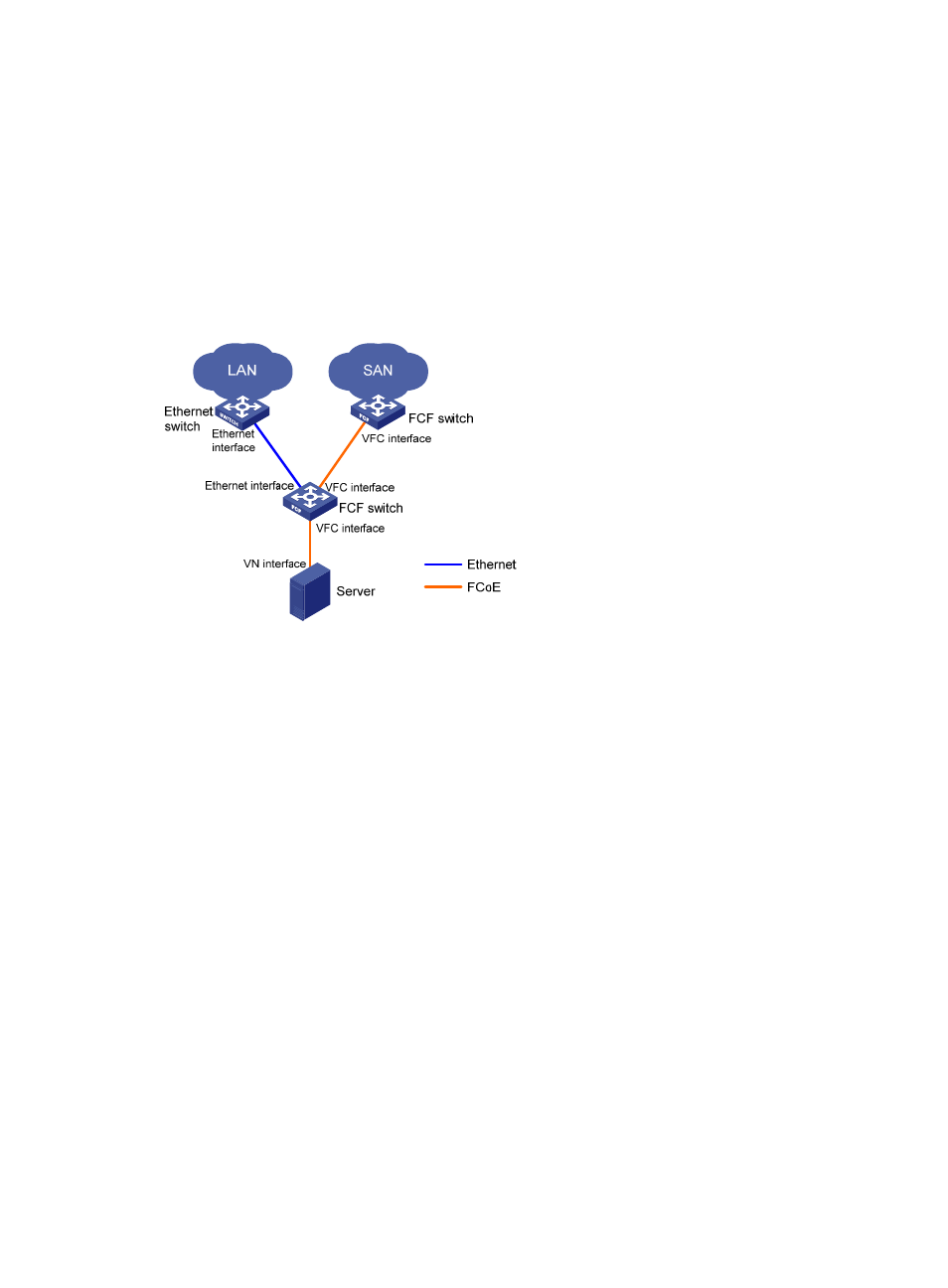
In the FCoE network, the server is connected to the LAN and SAN through one FCoE-capable FCF
switch. The link between the server and the FCF switch can transmit both Ethernet frames and FC
frames.
Basic concepts
As shown in
, the link between the FCF switch and the ENode can receive and send both Ethernet
frames and FC frames. ENodes can transport FC over Ethernet. ENodes include servers and disk
devices.
Figure 6 FCoE network diagram
VFC interface and VN interface
A virtual fibre channel (VFC) interface is a logical interface manually created on an FCF switch to
simulate the functionality of a physical FC interface.
To use a VFC interface, bind it to a physical Ethernet interface.
You can connect either an ENode or an FCF switch to a VFC interface.
VFC interfaces support E mode, F mode (default), and NP mode.
The virtual node (VN) interface is a logical interface on an ENode to simulate the function of a physical
FC interface.
FIP protocol
FCoE initialization protocol (FIP) is an FCoE control protocol that establishes and maintains virtual links.
FIP establishes a virtual link between the VFC interface of an FCF switch and either of the following:
•
A VN interface of an ENode.
•
A VFC interface of another FCF switch.
The virtual links provide a physical infrastructure for transmitting FC frames over Ethernet.
FCoE frames
To transmit an FC frame over Ethernet, FCoE encapsulates the FC frame in an FCoE frame by adding an
Ethernet frame header to the FC frame.
An FCoE frame uses Ethernet II encapsulation, which has the following fields in the Ethernet header: