Requirements analysis – H3C Technologies H3C S10500 Series Switches User Manual
Page 142
131
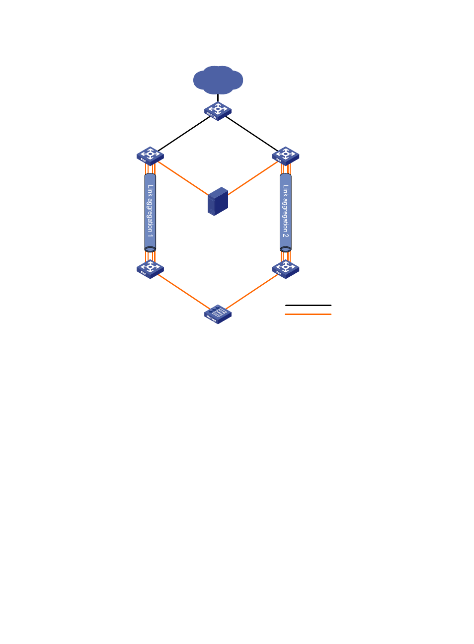
Figure 36 Network diagram
Requirements analysis
To transmit the storage traffic over lossless Ethernet links in the SANs, H3C recommends that you perform
the following tasks:
•
Configure DCBX, PFC in auto mode, and ETS on the Ethernet interfaces connecting the switches to
the server.
•
Configure DCBX and PFC in auto mode on the Ethernet interfaces connecting the switches to the
disk device.
•
Enable PFC by force on the Ethernet interfaces connecting switches.
To implement link backup between the server and the disk device, use two separate SANs to provide
connections between the server and the disk device. The two SANs can use the same VSAN. The two
separate VSANs are as follows:
•
One physical SAN is formed by the server, Switch A, Switch C, and the disk device.
•
The other physical SAN is formed by the server, Switch B, Switch D, and the disk device.
To transmit the Ethernet traffic of the LAN in VLAN 1001, configure the following interfaces to allow VLAN
1001:
•
The Ethernet interfaces connecting Switch A and Switch B to the LAN.
•
The Ethernet interfaces connecting Switch A and Switch B to the server.
Ethernet link
FCoE link
Ethernet
switch
FCF switch
LAN
FCF switch
FCF switch
FCF switch
Disk device
Server
XGE1/0/10
XGE1/0/1
XGE1/0/10
XGE1/0/1
VFC1
VFC1
XGE1/0/1
XGE1/0/1
VFC1
VFC1
XGE1/0/5 to XGE1/0/8
VFC10
XGE1/0/5 to XGE1/0/8
VFC10
VFC10
XGE1/0/5 to XGE1/0/8
VFC10
Switch B
Switch A
Switch D
Switch C
XGE1/0/5 to XGE1/0/8