Connectors labeling, Power connections, Figure 7: power connections – Precision Digital PD6200 User Manual
Page 20: Ma out, Power, Signal, M-link, Relay4 relay3, Relay2 relay1
Model PD6200 Analog Input Rate/Totalizer
Instruction Manual
20
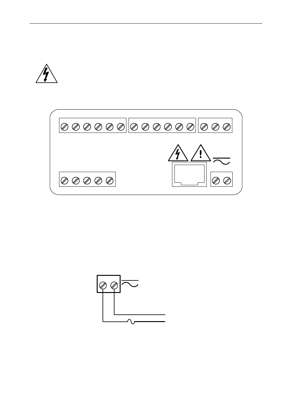
Connectors Labeling
The connectors’ label, affixed to the meter, shows the location of all con-
nectors available with requested configuration.
Warning!
Do not connect any equipment other than Precision
Digital’s expansion modules, cables, or meters to the
RJ45 M-LINK connector. Otherwise damage will occur
to the equipment and the meter.
DW1815
R
I-
I+
MA OUT
1
3
2
POWER
+
-
SIGNAL
P-
COM
P+
V+
mA+
3
4
1
2
5
M-LINK
C
NO
NO
NC
NC
C
RELAY4
RELAY3
4
3
6
5
2
1
C
NO
NO
NC
NC
C
RELAY2
RELAY1
4
3
6
5
2
1
1 2 3 4 5 6 7 8
2
1
Figure 6: Connector Labeling for Fully Loaded PD6200
Power Connections
Power connections are made to a two-terminal connector labeled POWER
on Figure 6. The meter will operate regardless of DC polarity connection.
The + and - symbols are only a suggested wiring convention.
AC or DC
POWER
Required External Fuse:
5 A max, 250 V Slow Blow
POWER
+
-
Figure 7: Power Connections