Interlock relay feature, Figure 17: digital i/o module connections, Figure 18. interlock connection – Precision Digital PD6200 User Manual
Page 26
Model PD6200 Analog Input Rate/Totalizer
Instruction Manual
26
1
2
3
4
5
6
+5
I1
I2
I3
I4
O1
7
8
O2
O3
9
10
O4
G
DI 1-4
DO 1-4
5 VDC
GND
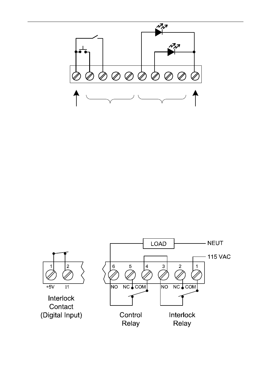
Figure 17: Digital I/O Module Connections
Interlock Relay Feature
As the name implies, the interlock relay feature reassigns one, or more,
alarm/control relays for use as interlock relay(s). Interlock contact(s) are
wired to digital input(s) and trigger the interlock relay. This feature is
enabled by configuring the relay, and relative digital input(s) (see page
66). In one example, dry interlock contacts are connected in series to
one digital input which will be used to force on (energize) the assigned
interlock power relay when all interlock contacts are closed (safe). The
interlock relay front panel LED flashes when locked out. The interlock
relay would be wired in-series with the load (N/O contact). See below.
Figure 18. Interlock Connection