Precision Digital PD6200 User Manual
Page 50
Model PD6200 Analog Input Rate/Totalizer
Instruction Manual
50
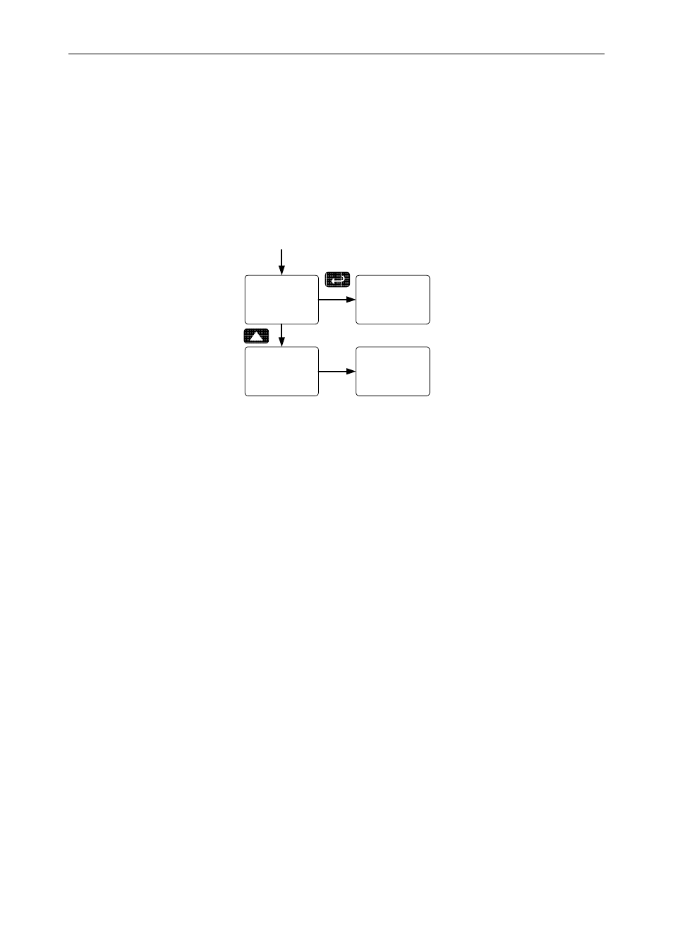
Programming Set and Reset Points
High alarm indication: program set point above reset point.
Low alarm indication: program set point below reset point.
The deadband is determined by the difference between set and reset
points. Minimum deadband is one display count. If the set and reset
points are programmed with the same value, the relay will reset one
count below the set point.
Note: Changes are not saved until the reset point has been accepted.
set 1
rly 1
rst 1
rly 1
Program
Set Point
Program
Reset Point
Setting Fail-Safe Operation
In fail-safe mode of operation, the relay coil is energized when the process
variable is within safe limits and the relay coil is de-energized when the
alarm condition exists. The fail-safe operation is set independently for each
relay. Select on to enable or select off to disable fail-safe operation.
Programming Time Delay
The On and Off time delays may be programmed for each relay between
0 and 999.9 seconds. The relays will transfer only after the condition has
been maintained for the corresponding time delay.
The On time delay is associated with the set point.
The Off time delay is associated with the reset point.
Relay Action for Loss of 4-20 mA Input (Loop Break)
The loop break feature is associated with the 4-20 mA input. Each relay
may be programmed to go to one of the following conditions when the
meter detects the loss of the input signal (i.e. < 0.005 mA):
1. Turn
On
(Go to alarm condition)
2. Turn
Off
(Go to non-alarm condition)
3. Ignore (Process as a low signal condition)
Note: This is not a true loop break condition; if the signal drops below
0.005 mA, it is interpreted as a “loop break” condition.