Meter operation – Precision Digital PD6200 User Manual
Page 87
Model PD6200 Analog Input Rate/Totalizer
Instruction Manual
87
METER OPERATION
The meter is capable of accepting current (0-20 mA, 4-20 mA) and vol-
tage signals (0-5 V, 1-5 V, 0-10 V,
10 V) and displaying these signals
in engineering units from -99999 to 999999 (e.g. a 4-20 mA signal could
be displayed as -50.000 to 50.000).
The dual-line display can be customized by the user to operate in such a
way as to satisfy a specific application. Typically the main display is used
for the process variable; while the second display is used for engineering
units, custom legend, total, grand total, or set point indication.
The meter can be set up to display the analog input on the main display
and the Modbus input on the second display. The relays and analog out-
put can be programmed to operate from the Modbus PV input.
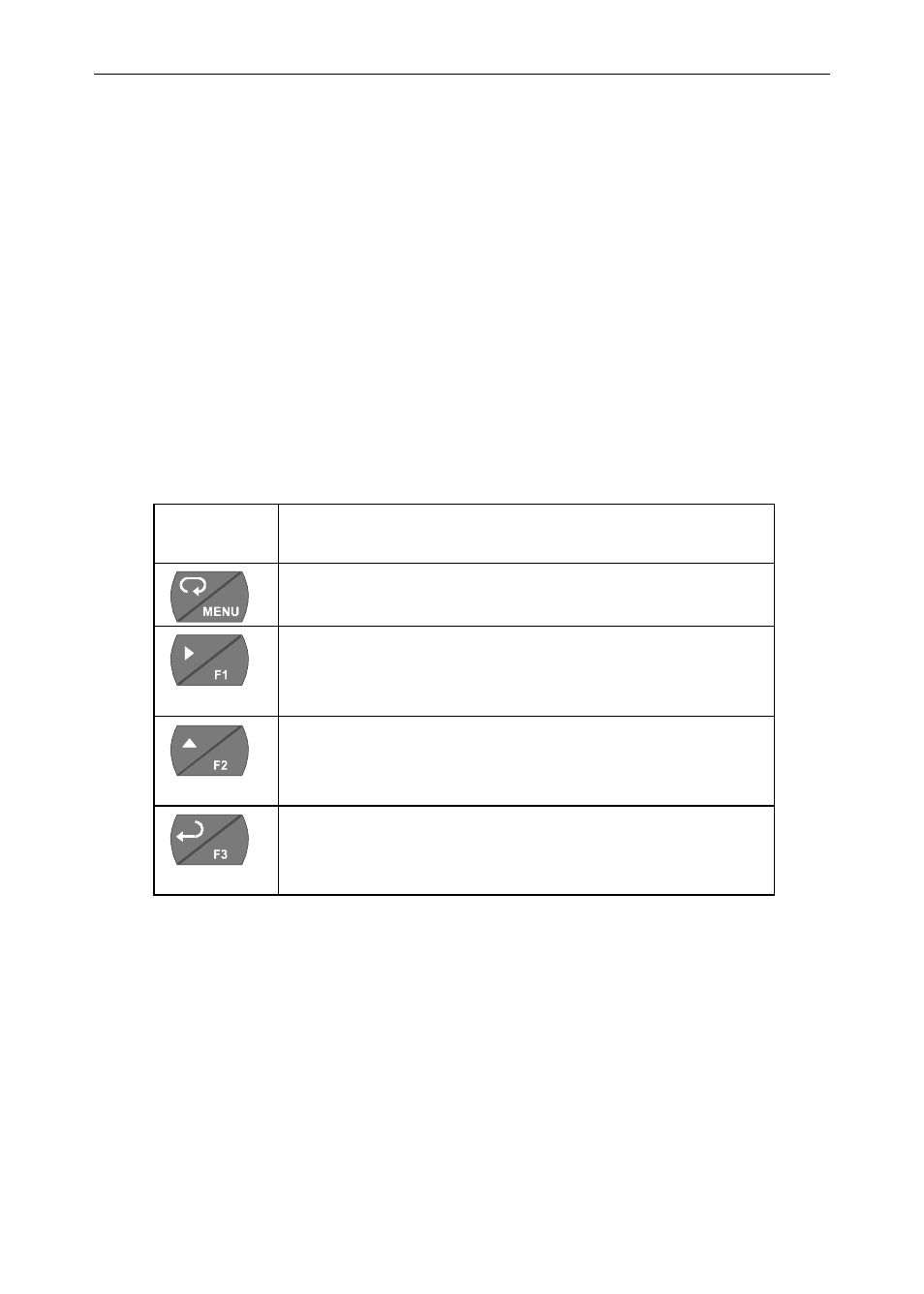
Front Panel Buttons Operation
Button
Symbol
Description
Press to enter or exit Programming Mode,
view settings, or exit max/min readings
Press to reset max/min readings or other
parameter/function assigned through the
User
menu
Press to display max/min readings or oth-
er parameter/function assigned through
the User menu
Press to acknowledge relays or other pa-
rameters/function assigned through the
User
menu
Function Keys Operation
During operation, the programmable function keys operate according to
the way they have been programmed in the Advanced Features – User
menu.
The table above shows the factory default settings for F1, F2, and F3.