Interrupt request/acknowledge cycle, Figure 8, Bus request/acknowledge cycle – Zilog Z08470 User Manual
Page 24
Architectural Overview
UM008007-0715
12
Z80 CPU
User Manual
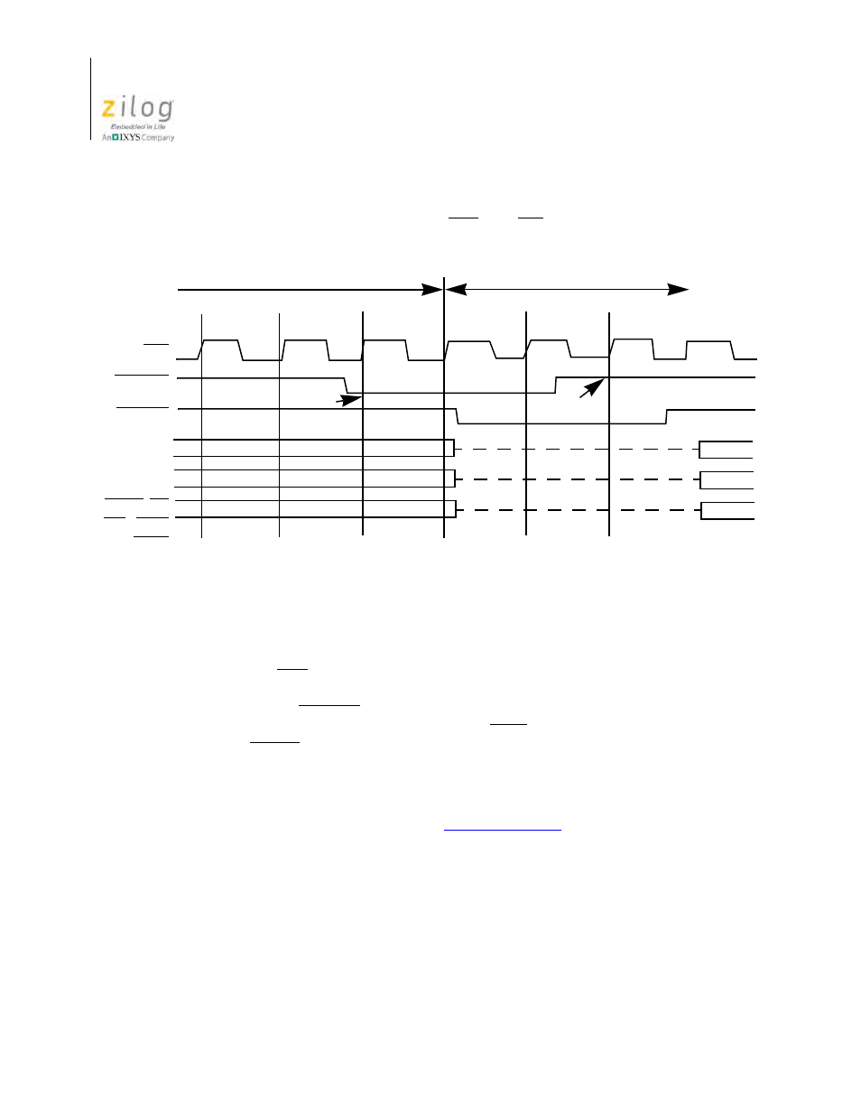
large blocks of data are transferred under DMA control. During a bus request cycle, the
CPU cannot be interrupted by either an NMI or an INT signal.
Interrupt Request/Acknowledge Cycle
Figure 9 shows the timing associated with an interrupt cycle. The CPU samples the inter-
rupt signal (INT) with the rising edge of the final clock at the end of any instruction. The
signal is not accepted if the internal CPU software controlled interrupt enable flip-flop is
not set or if the BUSREQ signal is active. When the signal is accepted, a special M1 cycle
is generated. During this special M1 cycle, the IORQ signal becomes active (instead of the
normal MREQ) to indicate that the interrupting device can place an 8-bit vector on the
data bus. Two wait states are automatically added to this cycle. These states are added so
that a ripple priority interrupt scheme can be easily implemented. The two wait states
allow sufficient time for the ripple signals to stabilize and identify which I/O device must
insert the response vector. Refer to the
more about how the interrupt response vector is utilized by the CPU.
Figure 8. Bus Request/Acknowledge Cycle
Sample
Sample
Floating
Last T State
Tx
Tx
Tx
T1
Any M Cycle
Bus Available Status
CLK
BUSREQ
MREQ, RD
BUSACK
WR. IORQ,
RFSH
A15 –A0
D7–D0