Interfacing dynamic memories, Figure 23. interfacing dynamic ram memory spaces – Zilog Z08470 User Manual
Page 37
UM008007-0715
Interfacing Dynamic Memories
Z80 CPU
User Manual
25
Interfacing Dynamic Memories
Each individual dynamic RAM space includes its own specifications that require minor
modifications to the examples provided here.
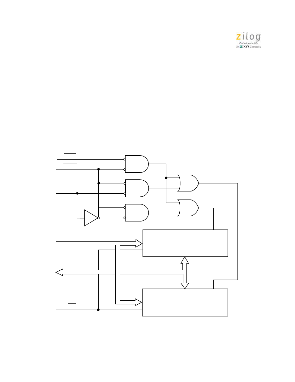
Figure 23 shows the logic necessary to interface 8 KB of dynamic RAM using 18-pin 4K
dynamic memories. This logic assumes that the RAMs are the only memory in the system
so that A12 is used to select between the two pages of memory. During refresh time, all
memories in the system must be read. The CPU provides the correct refresh address on
lines A0 through A6. When adding more memory to the system, it is necessary to replace
only the two gates that operate on A12 with a decoder that operates on all required address
bits. Address buffers and data bus buffers are generally required for larger systems.
Figure 23. Interfacing Dynamic RAM Memory Spaces
WR
R/W
R/W
CE
CE
4K x 8 RAM Array
Page 0
(0000 to 0FFFF)
4K x 8 RAM Array
Data Bus
Page 1
(1000 to 1FFFF)
D
7
–D
0
A
11
–A
0
RFSH
MREQ
A
12