2 pmc i/o module connectors, Transition module preparation and installation – Artesyn CPCI-6200 Installation and Use (May 2015) User Manual
Page 112
Transition Module Preparation and Installation
CPCI-6200 Installation and Use (6806800J66E)
112
5.5.2
PMC I/O Module Connectors
There are two pairs of 64-pin surface mount connectors on both the standard and MXP version
of the CPCI-6115-MCPTM to provide an interface for two optional add-on PMC I/O modules.
Each module has an identical PMC I/O connector and a unique Host I/O connector. All serial
port signals are at TTL levels. The pin assignments are as follows:
On the host I/O connectors, a PMC I/O module only uses power, ground and the OUT-going
serial port pins. A host I/O module could potentially use all pins except the OUT-going serial
port.
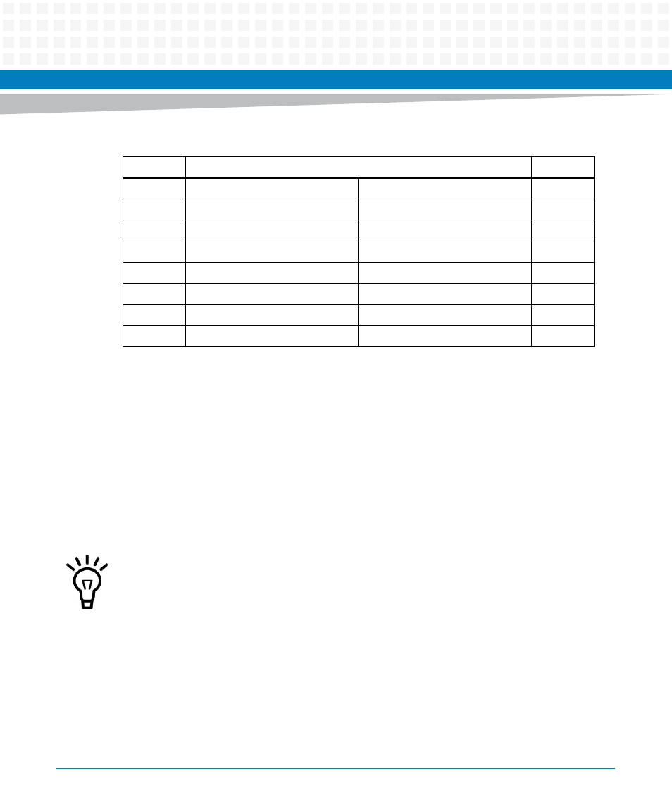
18
DA2
NO CONNECT
43
19
DA1
+5 V
44
20
DA0
DASP
45
21
DD0
PDIAG
46
22
DD1
DD8
47
23
DD2
DD9
48
24
NO CONNECT
DD10
49
25
NO CONNECT
GND
50
Table 5-3 CompactFlash IDE Connector Pin Assignments, J1 (continued)
Pin
J1
Pin
On the PMC I/O connector, pin meaning is defined entirely by the PMC residing on the host.
A host I/O module would not use any pins on this connector.