Memory maps and addresses, 1 default processor memory map, Table 8-1 – Artesyn CPCI-6200 Installation and Use (May 2015) User Manual
Page 185: Default processor address map, Ribed in, Chapter 8
Chapter 8
CPCI-6200 Installation and Use (6806800J66E)
185
Memory Maps and Addresses
8.1
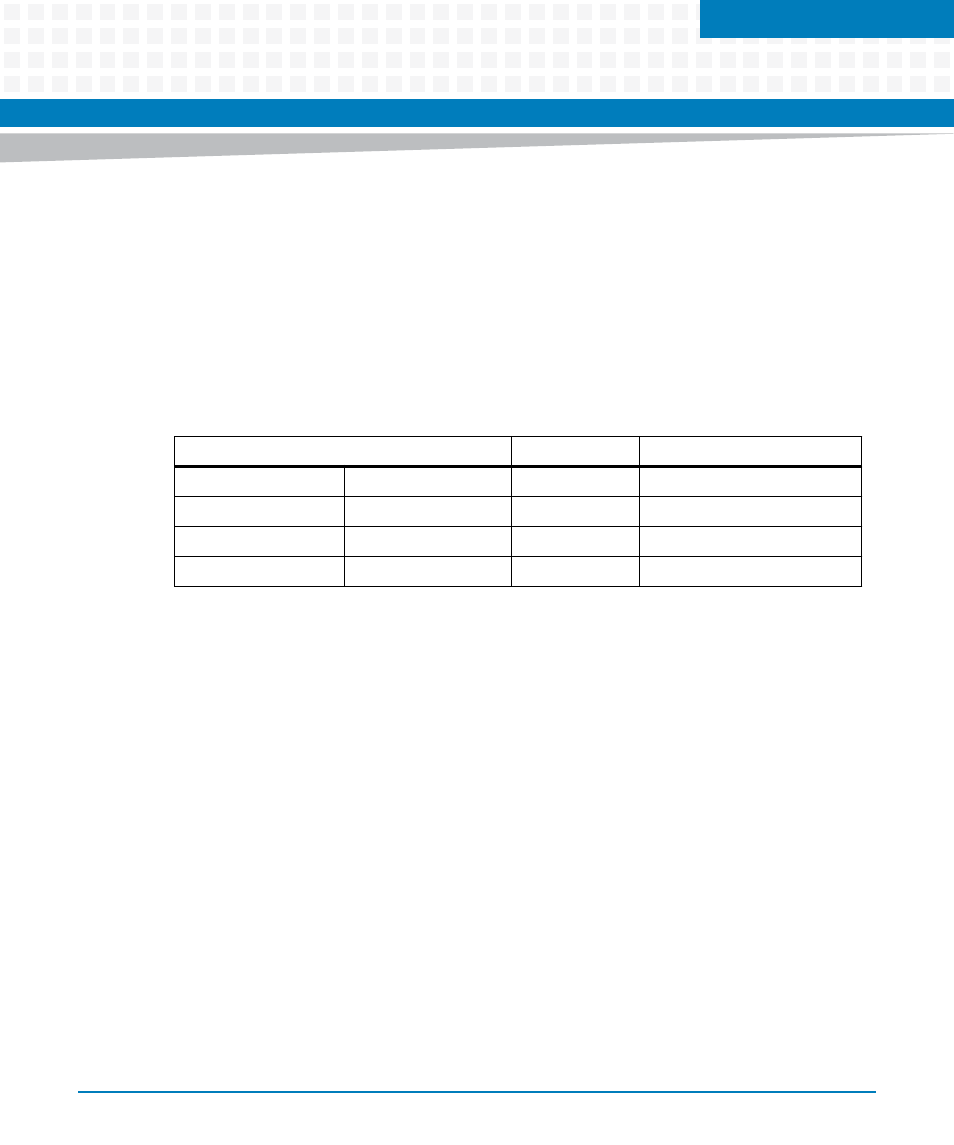
Default Processor Memory Map
The following table describes a default memory map from the point of view of the processor
after a processor reset. Note that the e500 core only provides one default TLB entry to access
boot code and it allows for accesses within the highest 4 KB of memory. In order to access the
full 8 MB of default boot space (and the 1 MB of CCSR space), additional TLB entries must be set
up within the e500 core for mapping these regions. For more information, see to the MPC8572
Reference Manual.
Table 8-1 Default Processor Address Map
Processor Address
Size
Definition
Start
End
0x0_0000_0000
0x0_FF6F_FFFF
4087 MB
Not mapped
0x0_FF70_0000
0x0_FF7F_FFFF
1 MB
MPC8572 CCSR Registers
0x0_FFF8_0000
0x0_FFFF_FFFF
8 MB
Flash