2 cpci bus connector, j2, Table 3-3, Cpci bus connector pinout, j2 – Artesyn CPCI-6200 Installation and Use (May 2015) User Manual
Page 61: Controls, leds, and connectors
Controls, LEDs, and Connectors
CPCI-6200 Installation and Use (6806800J66E)
61
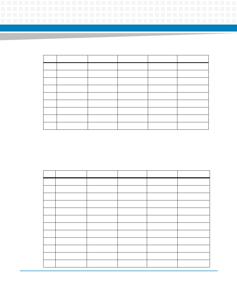
3.3.2
CPCI Bus Connector, J2
J2 is a five-row CPCI bus connector.
9
C/BE[3]#
IDSEL
AD[23]
GND1
AD[22]
8
AD[26]
GND
V(IO)
AD[25]
AD[24]
7
AD[30]
AD[29]
AD[28]
GND1
AD[27]
6
REQ#
GND
+3.3 V1
CLK
AD[31]
5
BRSVR1A5
BRSVR1B5
RST#
GND1
GNT#
4
IPMB_PWR
HEALTHY#
V(IO)1
INTP
INTS
3
INTA#
INTB#
INTC#
+5.0 V1
INTD#
2
TCK
+5.0 V
TMS
TDO
TDI
1
+5.0 V
-12 V
TRST#
+12 V
+5.0 V
Table 3-2 CPCI Bus Connector Pinout, J1 (continued)
Pin
Row A
Row B
Row C
Row D
Row E
Table 3-3 CPCI Bus Connector Pinout, J2
Pin
Row A
Row B
Row C
Row D
Row E
22
GA4
GA3
GA2
GA1
GA0
21
RSV
GND
RSV
RSV
RSV
20
RSV
GND
RSV
GND
RSV
19
GND
GND
RSV
RSV
RSV
18
BRSVP2A18
BRSVP2B18
BRSVP2C18
GND
BRSVP2E18
17
BRSVP2A17
GND
RSV
RSV
RSV
16
BRSVP2A16
BRSVP2B16
RSV
GND
BRSVP2E16
15
BRSVP2A15
GND
RSV
RSV
RSV
14
AD[35]
AD[34]
AD[33]
GND
AD[32]
13
AD[38]
GND
V(IO)
AD[37]
AD[36]
12
AD[42]
AD[41]
AD[40]
GND
AD[39]
11
AD[45]
GND
V(IO)
AD[44]
AD[43]