7 pci/pci-x configuration, Table 8-59, I2c bus device addressing – Artesyn CPCI-6200 Installation and Use (May 2015) User Manual
Page 223
Memory Maps and Addresses
CPCI-6200 Installation and Use (6806800J66E)
223
8.7
PCI/PCI-X Configuration
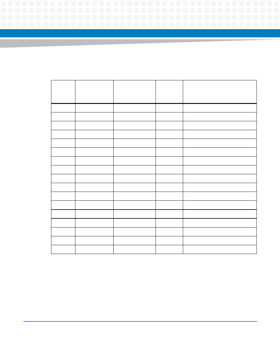
The following sections detail the PCI/PCI-X configuration of the onboard PCI devices.
Table 8-59 I
2
C Bus Device Addressing
I
2
C Bus
I
2
C Bus Address
Device Address
A2 A1 A0
(binary)
Size
(bytes)
Function
Bus 4
0xA0
000
N/A
Reserved
0xA2
001
256 x 8
DDR3 memory bank 1 SPD
1
1. Each SPD defines the physical attributes of each bank of memory.
0xA4
010
256 x 8
DDR3 memory bank 2 SPD
1
0xA6
011
64K x 8
User configuration 1
0xA8 / 0xAA
100
512 x 8
RTM VPD (off-board configuration)
0xAC
110
64K x 8
User configuration 2
0xAE
111
8K x 8
VPD (on-board configuration)
0xD0
N/A
N/A
M41T83 real-time clock
Bus 3
0x4C or 0x98
NA
N/A
ADT7461 temperature sensor
0xA0
000
64K x 8
User configuration
0xA2
001
64K x 8
VPD (on-board configuration)
0xA4
010
64K x 8
System Event Log (SEL)
0xA6
011
Reserved
0xA8
100
Reserved
0xAA
101
Reserved
0xAC
110
Reserved
0xAE
111
Reserved