17 pci express switch header, p7, 4 switches, 1 onboard switches – Artesyn CPCI-6200 Installation and Use (May 2015) User Manual
Page 78: Table 3-17, Pci express switch header pinout, p7, Controls, leds, and connectors
Advertising
Controls, LEDs, and Connectors
CPCI-6200 Installation and Use (6806800J66E)
78
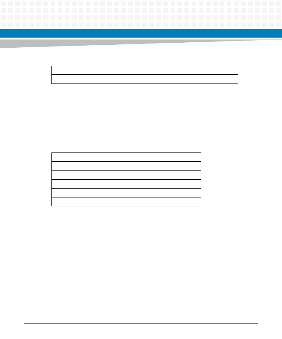
3.3.17 PCI Express Switch Header, P7
There is one standard 10-pin header located on the CPCI-6200 that provides the debug
capability of the PCI Express device PLX8624 using the I
2
C bus. The connector connects to the
Aardvark I
2
C/SPI Host Adapter. This header is only used for prototype debugging and is not
installed in the released product.
3.4
Switches
3.4.1
Onboard Switches
For information on switch settings, see
15
CPU_CKSTPO#
GND
16
Table 3-16 COP Header Pinout, P6 (continued)
Pin Number
Signal
Signal
Pin Number
Table 3-17 PCI Express Switch Header Pinout, P7
Pin Number
Signal
Signal
Pin Number
1
SCL
GND
2
3
SDA
NC
4
5
NC
NC
6
7
NC
NC
8
9
NC
GND
10
Advertising