3 local bus controller memory map, Table 8-3, Lbc memory map and chip select assignments – Artesyn CPCI-6200 Installation and Use (May 2015) User Manual
Page 187: Local bus, Controller memory map
Memory Maps and Addresses
CPCI-6200 Installation and Use (6806800J66E)
187
8.3
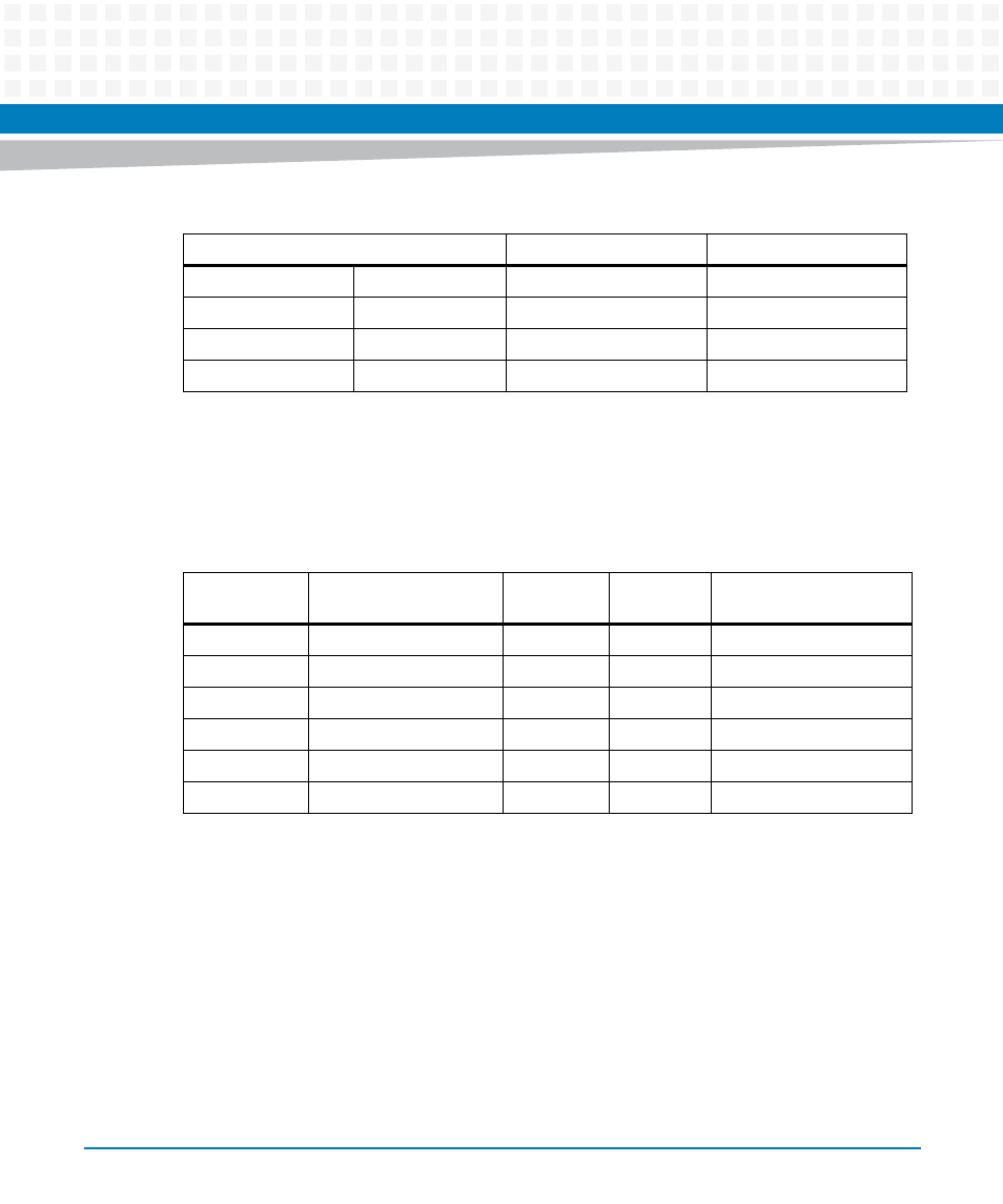
Local Bus Controller Memory Map
0x0_F0C0_0000
0x0_F0FF_FFFF
8 MB
PCI 1 I/O Space
0x0_F100_0000
0x0_F10F_FFFF
1 MB
MPC8572 CCSR
0x0_F110_0000
0x0_F1FF_FFFF
15 MB
Reserved
0x0_F200_0000
0x0_FFFF_FFFF
224 MB
Local Bus Controller
Table 8-2 CPCI-6200 Address Memory Map (continued)
Processor Address
Size
Definition
Table 8-3 LBC Memory Map and Chip Select Assignments
LBC Bank/Chip
Select
Local Bus Function
Size
Data Bus
Width
Address Range
0
Boot flash bank
128 MB
32 bits
F800_0000 - FFFF_FFFF
1
NAND flash bank
64 KB
8 bits
F203_0000 - F203_FFFF
2
MRAM
512 KB
16 bits
F240_0000 - F247_FFFF
3
Control/Status Registers
64 KB
32 bits
F200_0000 - F200_FFFF
4
Dual UART
64 KB
8 bits
F201_0000 - F201_FFFF
5
32-bit Timers
64 KB
32 bits
F202_0000 - F202_FFFF