2 control registers, Table 8-54, Tick timer control registers – Artesyn CPCI-6200 Installation and Use (May 2015) User Manual
Page 218: Table 8-55, Tick timer control field definition
Memory Maps and Addresses
CPCI-6200 Installation and Use (6806800J66E)
218
The prescaler provides the clock required by each of the four timers. The input clock to the
prescaler is 25 MHz. The default value is set for $E7 which gives a 1 MHz reference clock for a
25 MHz input clock source.
8.4.27.2 Control Registers
Tick Timer 1 Control Register—0xF202_0010 (32 bits)
Tick Timer 2 Control Register—0xF202_0020 (32 bits)
Tick Timer 3 Control Register—0xF202_0030 (32 bits)
Tick Timer 4 Control Register—0xF202_0040 (32 bits)
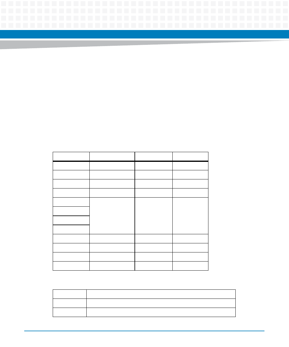
Table 8-54 Tick Timer Control Registers
Bit
Field
Operation
Reset
31:11
RSVD
R
0
10
INTS
R
0
9
CINT
R/W
0
8
EN_INT
R/W
0
7
OVF
R
0
6
5
4
3
RSVD
R
0
2
COVF
R/W
0
1
COC
R/W
0
0
ENC
R/W
0
Table 8-55 Tick Timer Control Field Definition
RSVD
Reserved
INTS
Interrupt Status
CINT
Clear Interrupt