17 cpci control and status register, Table 8-37, Cpci control/status register, 0xf200_0018 – Artesyn CPCI-6200 Installation and Use (May 2015) User Manual
Page 209: Table 8-38, Cpci control/status register field definition
Advertising
Memory Maps and Addresses
CPCI-6200 Installation and Use (6806800J66E)
209
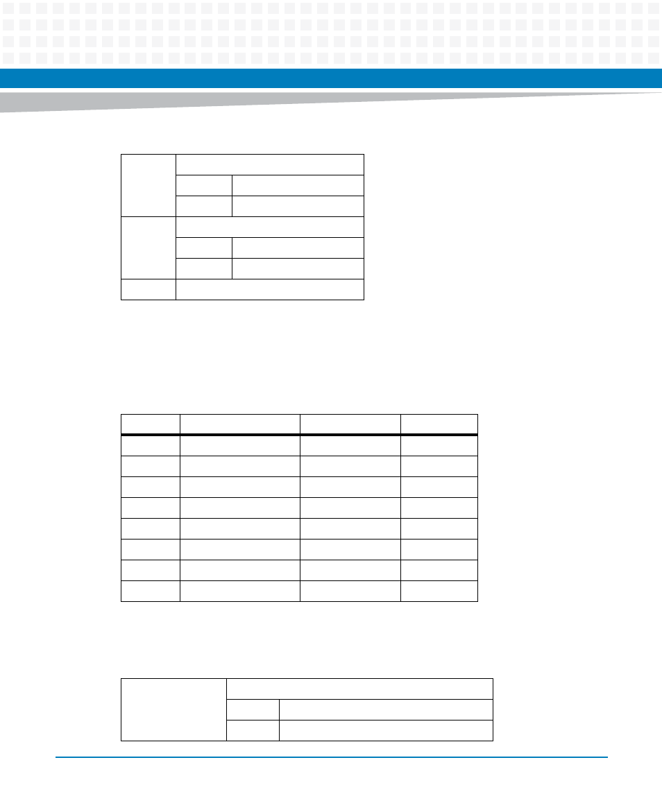
8.4.17 CPCI Control and Status Register
This register controls CPCI functions.
RB3
Ready/Busy 3
1
Device 3 is ready.
0
Device 3 is busy.
RB4
Ready/Busy 4
1
Device 4 is ready.
0
Device 4 is busy.
RSVD
Reserved
Table 8-36 NAND Flash Chip 2 Status Register Field Definition (continued)
Table 8-37 CPCI Control/Status Register, 0xF200_0018
Bit
Field
Operation
Reset
7
HS_LED_MASK
R/W
0
6
BP_RST_MASK
R/W
X
1
1. Reset value is 0 for system slot and 1 for peripheral slot.
5
HS_LED_ON
R/W
0
4
SA_MODE
R
0
3
SYS_EN_STS
R
X
2
RSVD
R
0
1
RSVD
R
0
0
RSVD
R
0
Table 8-38 CPCI Control/Status Register Field Definition
HS_LED_MASK
Hot Swap (Blue) LED Mask
1
Disable the illumination of Blue LED.
0
Enable the illumination of Blue LED.
Advertising